Disc type gas-liquid two-phase fluid uniform distribution device

A disc-type, gas-liquid technology, used in lighting and heating equipment, heat exchange equipment, heat exchanger shells, etc. problem, to achieve the effect of ensuring balanced connectivity, good uniform distribution, and low cost

Active Publication Date: 2020-11-06
CNOOC GAS & POWER GRP +1
View PDF7 Cites 0 Cited by
  • Summary
  • Abstract
  • Description
  • Claims
  • Application Information

AI Technical Summary

Problems solved by technology

However, the special working conditions at sea have a great influence on the heat transfer performance of the coiled tube heat exchanger. The prominent performance is that the shell side flow distribution of the coiled tube heat exchanger caused by sloshing is uneven and the bias flow is formed, which leads to the overall failure of the heat exchanger. The heat transfer efficiency drops, and even seriously deviates from the design conditions
As the inlet device of the shell side space of the coiled tube heat exchanger, the uniform distributor affects the flow field distribution of the incoming flow on the shell side, thereby affecting the efficiency of the heat exchanger and the liquefaction effect of natural gas
However, at present, there are few gas-liquid two-phase distribution structures suitable for coiled tube heat exchangers, and the liquid phase is mainly distributed evenly, and the gas phase is less involved.
The uneven flow of the gas phase in the space affects the uniformity of the liquid phase to a certain extent, and weakens the equalization effect of the distribution structure on the gas-liquid two-phase

Method used


Image

  • Disc type gas-liquid two-phase fluid uniform distribution device
  • Disc type gas-liquid two-phase fluid uniform distribution device

Examples


Embodiment Construction

[0021] It should be noted that, in the case of no conflict, the embodiments of the present invention and the features in the embodiments can be combined with each other.

[0022] The present invention will be described in detail below with reference to the accompanying drawings and examples.

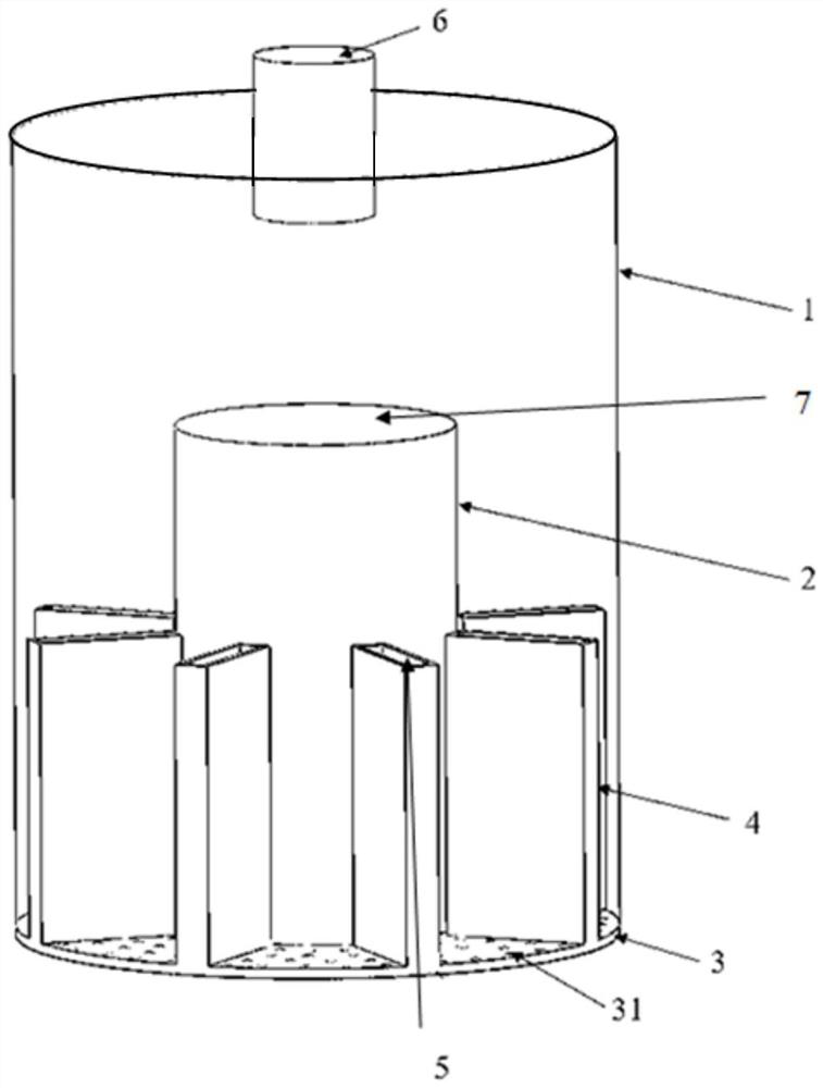
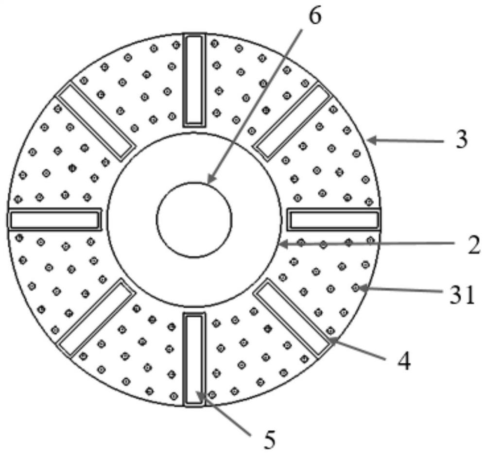
[0023] Such as Figure 1-Figure 2 As shown, a disc-type gas-liquid two-phase fluid uniform distribution device includes a vertically arranged shell cylinder 1, and a central cylinder 2 is arranged inside the shell cylinder 1, and the central cylinder The upper end of 2 is sealed by a baffle 7, and the lower outer wall of the central cylinder 2 is provided with a ring plate 3 tightly connected with the inner wall of the shell cylinder 1, and the ring plate 3 is uniformly provided with A plurality of flow equalization holes 31 are used to allow the liquid phase fluid to flow out uniformly; a number of stoppers 4 are evenly arranged between the outer shell cylinder 1 and the central cylind...


PUM


Abstract

The invention provides a disc type gas-liquid two-phase fluid uniform distribution device. The disc type gas-liquid two-phase fluid uniform distribution device comprises a vertically arranged shell barrel, a central barrel is arranged in the shell barrel, an upper end of the central barrel is sealed by a baffle, an external wall of a lower part of the central barrel is provided with a ring plate fastened and connected with an inner wall of the shell barrel, and a plurality of flow equalizing holes are uniformly formed on the ring plate; several stop dogs are uniformly arranged between the shell barrel and the central barrel, inside of each stop dog is hollow and two ends of each stop block are opening to form a gas phase channel, bottom ends of the several stop dogs are all fixedly connected with the ring plate, external side walls are all fixedly connected with the inner wall of the shell barrel, and a gap is arranged between internal side walls and the external wall of the central barrel. With the disc type gas-liquid two-phase fluid uniform distribution device, after outside gas-liquid phase fluid flows into the shell barrel, a gas-phase fluid flows into the gas phase channel and flows downwards through diffusion, a liquid-phase fluid falls freely and flows onto the ring plate and flows out through the flow equalizing holes, thus, a fluid gas-liquid phase uniform distribution channel is relatively independent, and the disc type gas-liquid two-phase fluid uniform distribution device has relatively better uniform distribution effect for the fluid having low air rate.

Description

technical field [0001] The invention belongs to the technical field of fluid uniform distribution, and in particular relates to a disc-type gas-liquid two-phase fluid uniform distribution device. Background technique [0002] As an important part of my country's energy development, natural gas is being studied on its storage and transportation methods. Offshore natural gas is extracted and liquefied and then transported back to land has become an important aspect of natural gas storage and transportation. The coiled tube heat exchanger is one of the main equipment for liquefied natural gas. It has the characteristics of high heat exchange efficiency and easy large-scale, and is suitable for the liquefaction of natural gas at sea. However, the special working conditions at sea have a great influence on the heat transfer performance of the coiled tube heat exchanger. The prominent performance is that the shell side flow distribution of the coiled tube heat exchanger caused by...

Claims


Application Information

Patent Timeline
Patent Type & Authority Applications(China)
IPC IPC(8): F28F9/22
CPCF28F9/22
Inventor 鹿来运花亦怀张晓慧姜益强郑文科田梦刘凯月汪耀龙
Owner CNOOC GAS & POWER GRP
Why Eureka
Try Eureka