
Active flow distribution type electromagnetic direct-drive hydrostatic brake unit and control method thereof

A technology of braking unit and control method, applied in the directions of brakes, braking transmissions, transportation and packaging, etc., can solve the problems of complex hydraulic pipelines and high energy consumption, and achieve high power transmission efficiency, huge economic benefits, and dynamic response. quick effect

Active Publication Date: 2020-11-06
SHANDONG UNIV OF TECH
View PDF5 Cites 0 Cited by
  • Summary
  • Abstract
  • Description
  • Claims
  • Application Information

AI Technical Summary

Problems solved by technology

[0005] The purpose of designing an active distribution type electromagnetic direct drive hydrostatic brake unit and its control method is to use a linear motor to directly drive the piston to reciprocate in the hydraulic cylinder, combined with The active flow distribution of the on-off valve realizes the pressurization, pressure maintenance and decompression of the brake wheel cylinder; combined with the advantages of electromagnetic direct drive and pump control direct drive, it has high efficiency, energy saving and quick response, which solves the problem of complex hydraulic pipelines and high energy consumption in the existing system. advanced questions

Method used


Image

  • Active flow distribution type electromagnetic direct-drive hydrostatic brake unit and control method thereof
  • Active flow distribution type electromagnetic direct-drive hydrostatic brake unit and control method thereof
  • Active flow distribution type electromagnetic direct-drive hydrostatic brake unit and control method thereof

Examples


Embodiment Construction

[0019] The present invention is further detailed below with reference to the accompanying drawings and specific embodiments.

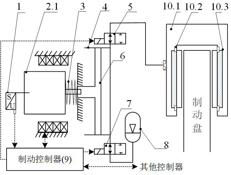
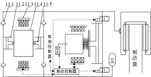
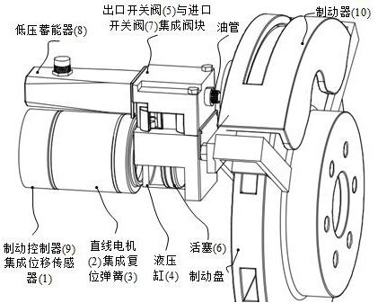
[0020] like figure 1 An active flow shown with electromagnetic direct drive hydrostatic braking unit and a control method comprising a displacement sensor (1), the linear motor (2), a return spring (3), the cylinder (4), the outlet switching valve (5 ), a piston (6), the switching valve inlet (7), low-pressure accumulator (8), brake controller (9), the brake (10), characterized by comprising: a linear motor mover (2.1) direct drive piston ( 6) in the cylinder (reciprocates outlet shutoff valve (5) 4), the inlet switching valve (7) is a normally open valve and are mounted between the cylinder (4) and the brake working chamber (10), a hydraulic cylinder (4) low-pressure accumulator and the working chamber (8); when the linear motor (2) does not operate, under action of the return spring (3) thrust piston (6) located at the end of the liquid suction stroke; b...


PUM


Abstract

The invention relates to an active flow distribution type electromagnetic direct-drive hydrostatic brake unit and a control method thereof. The active flow distribution type electromagnetic direct-drive hydrostatic brake unit comprises a displacement sensor, a linear motor, a reset spring, a hydraulic cylinder, an outlet switch valve, a piston, an inlet switch valve, a low-pressure energy accumulator, a brake controller and a brake. The brake unit is characterized in that the rotor of the linear motor directly drives the piston to reciprocate in the hydraulic cylinder, and the outlet switch valve and the inlet switch valve are normally open valves and are respectively mounted between the hydraulic cylinder and a brake and between the hydraulic cylinder and a low-pressure energy accumulator; when the linear motor does not work, the piston is located at the tail end of the liquid suction stroke under the action of thrust of the reset spring. The brake controller controls the movement ofthe linear motor, the outlet switch valve and the inlet switch valve according to the displacement information of the rotor of the linear motor according to the brake requirement so that the pressurization, the pressure maintaining and the pressure reduction of the brake wheel cylinder are realized; the advantages of electromagnetic direct drive and pump control direct drive are combined, high efficiency, energy conservation and quick response are achieved, and the problems that an existing system is complex in hydraulic pipeline, high in energy consumption and the like are solved.

Description

Technical field [0001] The present invention relates to the field of automotive brake-technology, particularly to a movable pump control unit. Background technique [0002] Auto industry after a hundred years of innovation and development, the use of conventional hydraulic brake system directly connected machine does not meet the development needs of the electric car, brake by wire (Brake-By-Wire) become the main development direction of automotive brake systems. [0003] The brake system includes two types of wire: wire-by-wire hydraulic brake system and mechanical braking systems. Wherein the mechanical brake-by-wire system completely abandon the hydraulic assembly, no mechanical backup to power as an energy source, but its development is still faced many problems such as motors, power, safety, and cost; wire-by-wire hydraulic brake system is relatively a mechanical braking system is easier to achieve lower development cost, when the electronic control unit still fails to ensur...

Claims


Application Information

Patent Timeline
IPC IPC(8): B60T13/12B60T13/66B60T13/74
CPCB60T13/12B60T13/66B60T13/745
Inventor 谭草葛文庆李波孙宾宾陆佳瑜秦琪晶
Owner SHANDONG UNIV OF TECH
Learn More