
Layered series-parallel DC power transmission system and DC fault clearing method thereof

A DC power transmission system and power transmission system technology, applied in the direction of converting AC power input to DC power output, AC network circuit, photovoltaic power generation, etc. Costs and operational losses, the effect of improving transmission efficiency, and improving grid flexibility

Active Publication Date: 2020-11-03
HUAZHONG UNIV OF SCI & TECH +2
View PDF5 Cites 0 Cited by
  • Summary
  • Abstract
  • Description
  • Claims
  • Application Information

AI Technical Summary

Problems solved by technology

[0009] The invention provides a layered hybrid direct current transmission system and a method for clearing direct current faults, which are used to solve the technical problem that the existing direct current transmission system is difficult to be compatible with low cost and high transmission efficiency

Method used


Image

  • Layered series-parallel DC power transmission system and DC fault clearing method thereof
  • Layered series-parallel DC power transmission system and DC fault clearing method thereof
  • Layered series-parallel DC power transmission system and DC fault clearing method thereof

Examples


Embodiment 1

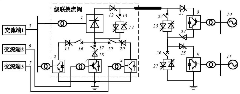
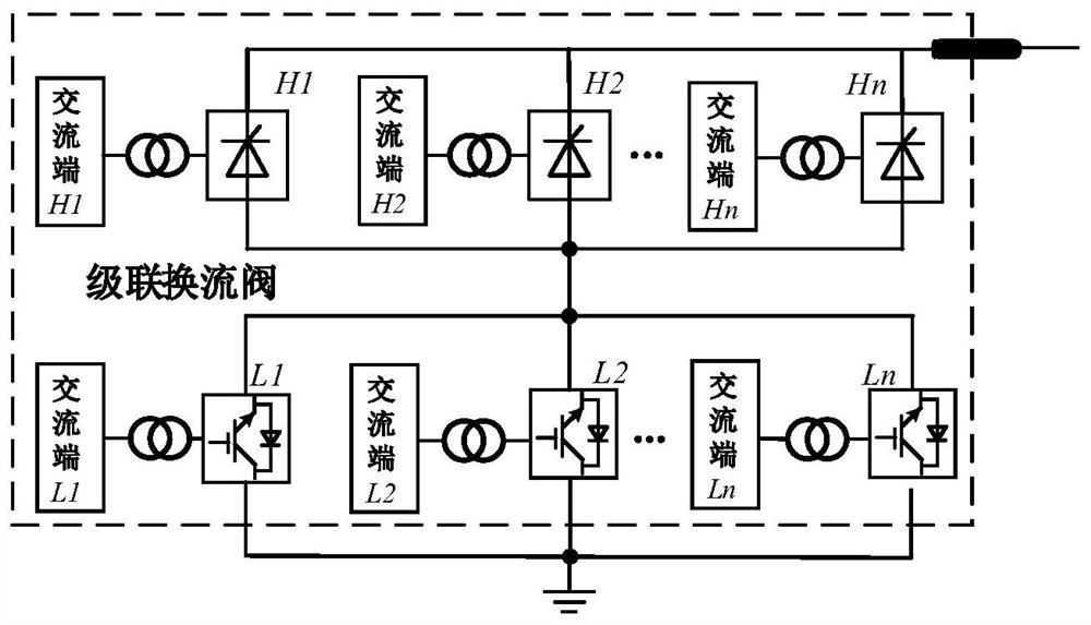
[0048] A layered hybrid direct current transmission system, including cascaded high-voltage valve groups and low-voltage valve groups on the rectification side, the high-voltage valve group includes n parallel-connected converters, and the low-voltage valve group includes m parallel-connected converters; each converter Connect the converters to the corresponding AC terminals respectively;

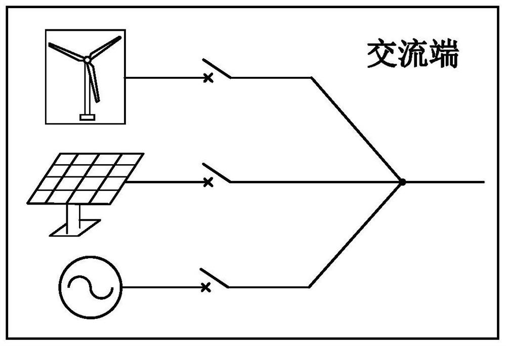
[0049] Wherein, each converter is independently connected to the AC terminal or multiple converters are connected to the same AC terminal, and the corresponding connection relationship between each converter and each AC terminal is determined by the type of each converter and the power transmission system The type and number of power grids at the AC end are determined.

[0050] The existing power transmission system can only realize the connection of a single new energy base, or the centralized connection of multiple new energy bases after exchange and collection, which is not conducive to ...

Embodiment 2

[0080] A method for clearing DC faults in the layered hybrid direct current transmission system as described in the first embodiment, which controls the cooperation of each converter in the layered hybrid direct current transmission system, and limits the fault current on the rectifier side and the inverter side When it is 0, clearing of the DC fault is completed. Preferably, when the transmission system is figure 1 As shown in the structure, and the converter in the high-voltage valve group on the rectification side is a grid-commutated converter, and the converter in the low-voltage valve group on the rectification side is a half-bridge modular multilevel converter, the troubleshooting methods include :

[0081] Judging whether there is a fault on the DC side of the power transmission system, blocking the modular multi-level converter in the power transmission system, thereby blocking the capacitor discharge path of the sub-module; switching the high-voltage valve group con...


PUM


Abstract

The invention belongs to the field of power transmission and distribution of power systems, and particularly discloses a layered series-parallel DC power transmission system and a DC fault clearing method thereof. The layered series-parallel DC power transmission system comprises a high-voltage valve bank and a low-voltage valve bank which are cascaded on the rectification side, the high-voltage valve bank comprises n converters connected in parallel, and the low-voltage valve bank comprises m converters connected in parallel; each current converter is connected with the corresponding alternating current end; each current converter is independently connected to the alternating current end or the plurality of current converters are jointly connected to the same alternating current end, andthe corresponding connection relationship between each current converter and each alternating current end is determined by the type of each current converter and the type and number of power grids atthe alternating current end of the power transmission system. In addition, the alternating current end can be an alternating current power grid or various new energy bases, and the cascade converter valve has various working modes. According to the invention, high-voltage, long-distance and high-capacity DC power transmission and multi-scale energy base layered access can be simultaneously realized on the premise of reducing the overall manufacturing cost of the DC system, and the power transmission efficiency and the power grid flexibility are improved.

Description

technical field [0001] The invention belongs to the technical field of electric power transmission and distribution, and more specifically relates to a layered hybrid direct current transmission system and a direct current fault clearing method thereof. Background technique [0002] Under the current background of prominent energy security issues and severe environmental pollution, in order to achieve low-carbon energy transformation, smog control and environmental protection, it is necessary to develop wind power and other renewable energy sources. By the end of 2019, the cumulative installed capacity of wind power in the country was 210 million kilowatts, accounting for 10.4% of the total installed capacity of power generation, of which the cumulative installed capacity of onshore wind power was 204 million kilowatts. With the rapid increase of onshore wind power installed capacity, it is very important to study the selection of converters suitable for long-distance and la...

Claims


Application Information

Patent Timeline
IPC IPC(8): H02J3/36H02M7/483H02J3/38H02H7/26
CPCH02J3/36H02M7/483H02J3/381H02J3/388H02H7/26H02J2300/24H02J2300/28H02M7/4835Y02E60/60Y02E10/56
Inventor 孟沛彧向往迟永宁王志冰荆江平文劲宇
Owner HUAZHONG UNIV OF SCI & TECH
Learn More