
Hammer type crusher capable of improving crushing efficiency

A hammer crusher, high-efficiency technology, applied in the direction of grain processing, etc., can solve the problems of easy damage of the sieve plate, wear of the end of the breaking hammer, and affecting the efficiency of sieving powder, so as to improve the crushing effect, prolong the service life, and improve the crushing efficiency. efficiency effect

Active Publication Date: 2020-11-06
徐州中矿汇弘矿山设备有限公司
View PDF15 Cites 10 Cited by
  • Summary
  • Abstract
  • Description
  • Claims
  • Application Information

AI Technical Summary

Problems solved by technology

[0003] However, the existing hammer crusher still has the following technical problems in the actual use process: firstly, the crushed material is screened by setting a sieve plate, and the material with a larger particle size is left on the sieve plate to be used as a hammerhead. When re-crushing materials with larger particle sizes, the hammer head will hit the sieve plate through the material, causing the sieve plate to be easily damaged, seriously affecting the powder screening efficiency, and reducing the working efficiency of the hammer crusher; During the process, the wear of the breaker is serious, and the striking efficiency is not high. The main reason is that during continuous feeding, the end of the hammer head away from the drive shaft contacts and collides with the mineral for a long time, resulting in sliding friction, which causes the breaker to break. The end wear is serious, and the end wear is serious, and the distance between the breaking hammer and the sieve plate and the crushing plate will be increased, resulting in some larger particles that cannot be crushed again, which seriously affects the crushing efficiency. Maximum efficiency and minimum wear when struck sideways by the hammer

Method used


Image

  • Hammer type crusher capable of improving crushing efficiency
  • Hammer type crusher capable of improving crushing efficiency
  • Hammer type crusher capable of improving crushing efficiency

Examples


Embodiment Construction

[0019] The following will clearly and completely describe the technical solutions in the embodiments of the present invention with reference to the accompanying drawings in the embodiments of the present invention. Obviously, the described embodiments are only some, not all, embodiments of the present invention. Based on the embodiments of the present invention, all other embodiments obtained by persons of ordinary skill in the art without making creative efforts belong to the protection scope of the present invention.

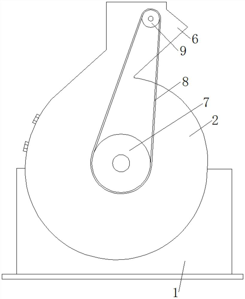
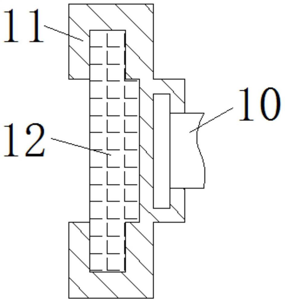
[0020] see Figure 1-5 , including a base 1, the upper end of the base 1 is fixedly connected with a volute 2, the top of the volute 2 is fixedly connected with a feed inlet 6, the middle part of the volute 2 is movably socketed with a transmission shaft 3, and the middle part of the transmission shaft 3 is fixedly connected with a The rotor 4 is fixedly installed with several groups of breakers 5 installed on the outer side of the rotor 4. The end of the tran...


PUM


Abstract

The invention relates to the technical field of mineral processing equipment, and discloses a hammer type crusher capable of improving crushing efficiency. The hammer type crusher comprises a base, wherein the upper end of the base is fixedly connected to volute casing; a feeding hole is fixedly connected above the volute casing; and the middle part of the volute casing movable sleeves a transmission shaft. A bracket, a spring and a supporting plate are arranged, so that a hammer head hits against a sieve plate through materials while the hammer head of the crushing hammer re-crushes materialswith greater particle diameters, which drop onto the sieve plate; damages on the sieve plate by the hammer head are reduced by damping, extending and retracting of the spring, so that the sieve plateis protected, and the service life of the sieve plate is prolonged; while part of relatively great particles are pressed along with the sieve plate, the spring rebounds after the crushing hammer rotates through the materials for throwing the materials, so that the materials are directly crushed by the crushing hammer, and therefore, crushing efficiency is improved; and meanwhile, the spring can be arranged, so that the sieve plate is always in a shaking and vibrating state, and therefore, the sieving process can be quickened, and sieving effect can be improved.

Description

technical field [0001] The invention relates to the technical field of mineral processing equipment, in particular to a hammer crusher for improving crushing efficiency. Background technique [0002] The existing hammer crusher mainly includes a box body, a rotor arranged in the box body and a motor driving the rotor to rotate. The inner wall of the box body is also provided with a counter-attack crushing plate; the top of the box body is provided with a feeding pipe, and the bottom of the box body There is a sieve plate; there are several hammers on the rotor. When in use, start the motor, and the motor drives the rotor to rotate, so that the rotor drives the hammer to rotate, and then puts the material into the box. The high-speed impact of the hammer rotates the material so that the material is At the same time, a part of the material hits the counter-attack crushing plate under the action of the hammer head, and the counter-attack crushing plate gives the material a reac...

Claims


Application Information

Patent Timeline
Patent Type & Authority Applications(China)
IPC IPC(8): B02C13/13B02C13/04B02C13/30B02C13/286
CPCB02C13/13B02C13/04B02C13/30B02C13/286B02C2013/28618
Inventor 周斌
Owner 徐州中矿汇弘矿山设备有限公司
Learn More