Driving chip and display device

A technology for driving chips and display panels, applied in static indicators, instruments, etc., can solve problems such as damage to the driver chip and uneven force on the driver chip

Active Publication Date: 2020-11-03
XIAMEN TIANMA MICRO ELECTRONICS
View PDF9 Cites 10 Cited by
  • Summary
  • Abstract
  • Description
  • Claims
  • Application Information

AI Technical Summary

Problems solved by technology

[0004] The present invention provides a driving chip and a display device to improve the problem of uneven stress on the driving chip during the binding process and avoid damage to the driving chip

Method used


Image

  • Driving chip and display device
  • Driving chip and display device
  • Driving chip and display device

Examples


Embodiment Construction

[0028] In order to further explain the technical means and effects of the present invention to achieve the intended purpose of the invention, the specific implementation, structure and characteristics of a driving chip and a display device proposed according to the present invention will be described below in conjunction with the accompanying drawings and preferred embodiments. And its effect, detailed description is as follows.

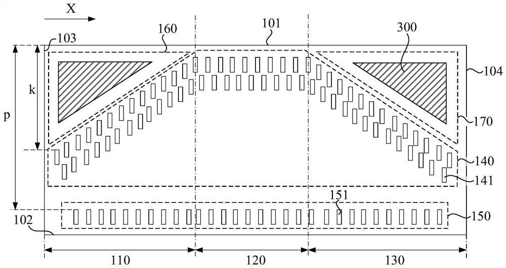
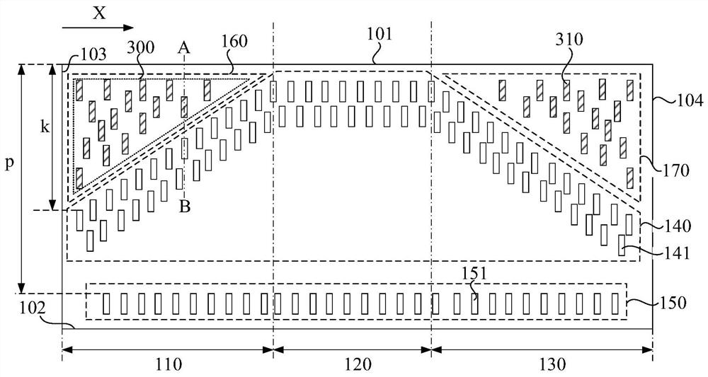
[0029] An embodiment of the present invention provides a driver chip, including:

[0030] An output terminal group and an input terminal group; the output terminal group includes a plurality of output terminals; the input terminal group includes a plurality of input terminals;

[0031] The driver chip includes a first side, a second side, a third side and a fourth side; the first side is opposite to the second side; the third side is opposite to the fourth side; the third side is respectively connected to The first side is connected to the second si...


PUM


Abstract

The invention discloses a driving chip and a display device. The driving chip comprises a first region, a second region and a third region; in the first direction, the distance between each output terminal located in the first area and the first edge is gradually reduced, and the distance between each output terminal located in the third area and the first edge is gradually increased; the distances between the output terminals in the second area and the first side are equal and are less than the distances between the first area and the first side of the output terminals in the second area; thedistances between the input terminals and the first side are equal; the output terminal group is located between the input terminal group and the first side; heightening layers are arranged in an area surrounded by the output terminal, the first edge and the third edge of the first area and an area surrounded by the output terminal, the first edge and the fourth edge of the third area, wherein the first direction is parallel to the plane where the driving chip is located and the first edge of the driving chip. According to the technical scheme provided by the embodiment of the invention, theproblem of uneven stress of the driving chip is improved, and the driving chip is prevented from being damaged.

Description

technical field [0001] Embodiments of the present invention relate to the field of display technology, and in particular, to a driving chip and a display device. Background technique [0002] The driver chip is used to provide various driving signals required for the normal operation of the display panel, and is one of the important components of the display device. [0003] The driver chip is usually mounted on the display panel in a chip on glass (COG) manner. Specifically, the driver chip includes a plurality of input terminals and a plurality of output terminals, and the display panel includes a plurality of input bonding pads and a plurality of The output binding pads, the input binding pads are electrically connected to the input terminals in one-to-one correspondence, and the output binding pads are electrically connected to the output terminals in one-to-one correspondence. Both the input terminal and the output terminal of the driver chip have a raised structure, a...

Claims


Application Information

Patent Timeline
IPC IPC(8): G09G3/20
CPCG09G3/20
Inventor 戴佳华陆利丰黄敏
Owner XIAMEN TIANMA MICRO ELECTRONICS
Why Eureka
Try Eureka