Durability testing system and method for hydraulic control unit in automobile braking system

An automotive braking system and control unit technology, applied in vehicle testing, machine/structural component testing, measuring devices, etc., can solve problems affecting the stability of HCU use, and achieve improved efficiency and consistency of braking characteristics stable effect

Active Publication Date: 2020-11-03
TSINGHUA UNIV
View PDF9 Cites 0 Cited by
  • Summary
  • Abstract
  • Description
  • Claims
  • Application Information

AI Technical Summary

Problems solved by technology

[0005] At present, most of the HCU performance test benches are related to the static characteristics and dynamic performance of the HCU, such as the sealing of the solenoid valve, the response time of the solenoid valve, the pressure increase and decrease capacity of the plunger pump, etc., and do not involve the test of the durability of the HCU. Thus directly affecting the evaluation of the stability of HCU use

Method used


Image

  • Durability testing system and method for hydraulic control unit in automobile braking system
  • Durability testing system and method for hydraulic control unit in automobile braking system
  • Durability testing system and method for hydraulic control unit in automobile braking system

Examples


Embodiment 1

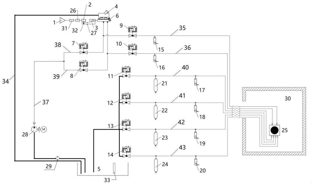
[0041] Such as figure 1 As shown, the embodiment of the present invention provides a durability test system for a hydraulic control unit in an automobile braking system, including: an air pressure supply system, an air pressure pipeline system, a measurement and control system, and an environment simulation system.

[0042] The air pressure supply system includes an air source 1 , a two-position five-way solenoid valve 2 and a cylinder 3 connected in sequence through pipelines.

[0043]The pneumatic pipeline system includes an oil pot 4, a fuel tank 5, a master cylinder 6, a pneumatic ball valve 7-14, a pressure sensor 15-20 and a simulated wheel cylinder 21-24, and the cylinder 3 is connected to the master cylinder 6 by pushing; The overflow port of the oil pot 4 is connected with the oil tank 5 through the return line 34, the oil outlet of the oil pot 4 is connected with the oil inlet of the master cylinder 6, and the two outlets of the master cylinder 6 The oil ports are r...

Embodiment 2

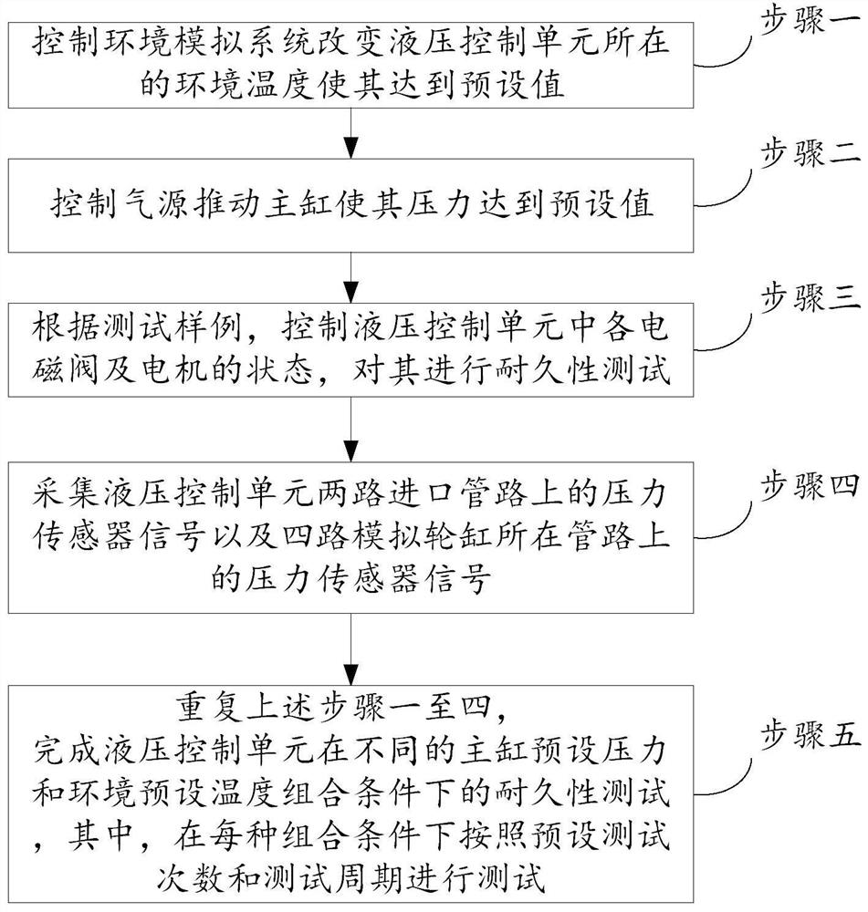
[0098] Such as figure 2 As shown, the embodiment of the present invention provides a method for testing the durability of a hydraulic control unit in an automobile braking system, including:

[0099] Step 1, the control environment simulation system changes the ambient temperature where the hydraulic control unit is located to reach a preset value;

[0100] Step 2, control the air source to push the master cylinder to make its pressure reach the preset value;

[0101] Step 3, according to the test sample, control the state of each solenoid valve and motor in the hydraulic control unit, and perform a durability test on it;

[0102] Step 4, collecting the pressure sensor signals on the two inlet pipelines of the hydraulic control unit and the pressure sensor signals on the pipelines where the four simulated wheel cylinders are located;

[0103] Step 5, repeat the above steps 1 to 4 to complete the durability test of the hydraulic control unit under different combinations of m...


PUM


Abstract

The invention discloses a durability test system and method for a hydraulic control unit in an automobile brake system. The system comprises an air pressure supply system, an air pressure pipeline system, a measurement and control system and an environment simulation system. According to the system and the method, an air source is adopted as a pressure source, so that rapid pressure rise and fallare realized, and reciprocating change of pressure can be borne; besides, the simulation wheel cylinder is adopted, so that the reciprocating change of pressure can be borne, and the consistency of braking characteristics is more stable. The system and the method can achieve automatic exhaust treatment on the hydraulic control unit, monitor the pressure of a main cylinder and a wheel cylinder of the system, provide environment temperature, achieve automatic control on the states of electromagnetic valves and motors of the hydraulic control unit, and improve the durability test efficiency of the hydraulic control unit.

Description

technical field [0001] The invention relates to the technical field of quality detection of components in an automobile braking system, in particular to a durability performance testing system and method for a hydraulic control unit in an automobile braking system. Background technique [0002] The hydraulic control unit (HCU) is the executive component of the anti-lock brake control system (ABS) pressure adjustment. If the execution effect of the HCU is poor, it will directly affect the braking safety. [0003] In order to prevent locking, the electronic control unit (ECU) issues high-frequency commands. Therefore, in order to be able to respond to the commands of the ECU, the HCU needs to have a high response frequency, that is, the solenoid valve has a high response frequency to complete the pressurization and maintenance. Compression and decompression actions. [0004] HCU is composed of booster valve, pressure reducing valve, return pump, damper, pump motor, low pressu...

Claims


Application Information

Patent Timeline
Patent Type & Authority Applications(China)
IPC IPC(8): G01M17/007
CPCG01M17/007
Inventor 穆洪远李亮高祥
Owner TSINGHUA UNIV
Why Eureka
Try Eureka