
Circulating fluidized bed heat supply unit slag cooler and low-temperature economizer heat utilization system

A low-temperature economizer and circulating fluidized bed technology, applied in heating systems, fluidized bed combustion equipment, space heating and ventilation, etc., can solve the problem of reducing the operating efficiency of low-pressure heaters in steam turbine systems and reducing Issues such as the outlet water temperature of the deaerator and the impact on the thermal efficiency of the power station can achieve the effect of improving the utilization rate of heat, ensuring stability, and ensuring cleanliness

Pending Publication Date: 2020-11-03
李广建
View PDF0 Cites 2 Cited by
  • Summary
  • Abstract
  • Description
  • Claims
  • Application Information

AI Technical Summary

Problems solved by technology

[0003] However, this production method has certain defects. First, the thermal efficiency of the recovered heat from the slag cooler and the low-temperature economizer is low under the pure condensing condition of the power station; The reduction of steam volume will reduce the operating efficiency of the low-pressure heater of the steam turbine system, thereby reducing the temperature of the condensed water to the outlet water of the deaerator, and affecting the thermal efficiency of the power station

Method used


Image

  • Circulating fluidized bed heat supply unit slag cooler and low-temperature economizer heat utilization system

Examples

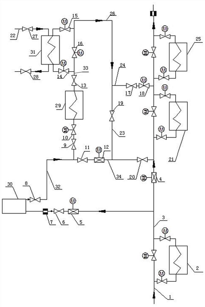

Embodiment Construction

[0024] The present invention will be further described in detail below in conjunction with the accompanying drawings and specific embodiments.

[0025] Such as figure 1 As shown, the heat utilization system of the slag cooler and low-temperature economizer of the circulating fluidized bed heating unit includes the slag cooler 30, the low-temperature economizer 29, and #3 low-pressure heaters 2 and #2 that heat the condensed water step by step Low pressure heater 21 and #1 low pressure heater 25. The condensed water is heated by the #3 low-pressure heater 2 and sent to the slag cooler 30 to cool the cinder in the slag cooler, and the slag cooler 30 and the low-temperature economizer 29 are also connected in series through the slag cooler outlet pipe 32 Therefore, the condensed water can recover the heat of the slag cooler 30 and the low-temperature economizer 29 at the same time through one cycle, further increase the temperature of the condensed water, and improve the efficie...


PUM


Abstract

The invention relates to a circulating fluidized bed heat supply unit slag cooler and low-temperature economizer heat utilization system which comprises a slag cooler, a low-temperature economizer, a#3 low-pressure heater, a #2 low-pressure heater and a #1 low-pressure heater, wherein the #3 low-pressure heater, the #2 low-pressure heater and the #1 low-pressure heater are used for heating condensed water step by step, the condensed water is heated through the #3 low-pressure heater to be then conveyed to the slag cooler, and the slag cooler and the low-temperature economizer are connected inseries through a slag cooler water outlet pipeline; the circulating fluidized bed heat supply unit slag cooler and low-temperature economizer heat utilization system further comprises a plate heat exchanger, the plate heat exchanger is used for exchanging heat of urban heat supply network circulating water, the plate heat exchanger is connected with the low-temperature economizer in series through a low-temperature economizer water outlet pipeline, and the condensed water inlet end and the condensed water outlet end of the plate heat exchanger are connected with a plate heat exchanger bypasspipeline in parallel; and a water outlet of the plate heat exchanger bypass pipeline is respectively communicated with water inlet pipelines of the #1 low-pressure heater and the #2 low-pressure heater. By means of the circulating fluidized bed heat supply unit slag cooler and low-temperature economizer heat utilization system, the heat utilization rate of the slag cooler and the low-temperature economizer can be increased, and the operation efficiency of the low-pressure heaters and the thermal efficiency of a power station are improved.

Description

technical field [0001] The invention relates to the technical field of circulating fluidized bed boilers, in particular to a heat utilization system for a slag cooler and a low-temperature economizer of a circulating fluidized bed heating unit. Background technique [0002] The circulating fluidized bed heating unit has wide fuel adaptability, high combustion efficiency, efficient desulfurization, NO x It has many advantages such as low emission, simple structure, and convenient operation, so it is widely used in the field of electric power. At present, in the thermal production of circulating fluidized bed boilers, condensed water is usually used to absorb the heat of the slag cooler and low-temperature economizer in the boiler system, and then the recovered heat is transferred to the condensed water system. [0003] However, this production method has certain defects. First, the thermal efficiency of the recovered heat from the slag cooler and low-temperature economizer i...

Claims


Application Information

Patent Timeline
IPC IPC(8): F23C10/18F24D3/02F24D3/10F24D19/10F28D21/00
CPCF23C10/18F24D3/02F24D3/1058F24D19/1015F28D21/0001
Inventor 李广建艾护民代军伟李向东袁洪杰常书伟徐芝敏齐明飞樊同宾寇记锋王远明李保新梁庆涛王海涛赵晨凯王璐刘少革崔国岭潘永军杨运超化建耀郑勇全国华
Owner 李广建
Learn More