Motor rotor die-casting manufacturing process

A motor rotor and manufacturing process technology, applied in the field of motor parts processing, can solve problems such as reducing the stacking accuracy of lamination assembly, reducing motor torque due to eddy current damage, and damage to motor rotor laminations.

Active Publication Date: 2020-11-03
威海立安精密铸造有限公司
View PDF10 Cites 7 Cited by
  • Summary
  • Abstract
  • Description
  • Claims
  • Application Information

AI Technical Summary

Problems solved by technology

The motor rotor is mainly composed of iron core, rotor winding and rotating shaft. Since a thicker large iron core will cause greater eddy current damage and reduce the motor torque, the motor rotor is usually composed of several ferromagnetic conductor sheets. As a result, the eddy current loss can be significantly reduced, so the motor rotor widely adopts the laminated iron core structure; in order to adapt to mass production, the motor rotor laminates can be processed by punching or die-casting. During the forming process, the burrs cannot be completely avoided at the position of the slot hole on the motor rotor sheet for winding the rotor winding, and the surface of the motor rotor laminations needs to be coated with an insulating coating. The burrs on the motor rotor laminations will not only affect the coating. layer effect and appearance aesthetics, and will reduce the accuracy of lamination assembly and stacking, resulting in the failure of the motor rotor laminations to form a tight lamination structure, so it is necessary to further treat the surface of the motor rotor laminations after die-casting. In the traditional In the process of processing, manual grinding is often used, the efficiency of manual processing is very low, and improper grinding techniques will cause damage to the motor rotor laminations, thus affecting the dimensional accuracy and appearance aesthetics to a certain extent

Method used


Image

  • Motor rotor die-casting manufacturing process
  • Motor rotor die-casting manufacturing process
  • Motor rotor die-casting manufacturing process

Examples


Embodiment Construction

[0035] The specific embodiment of the present invention will be described in further detail by describing the embodiments below with reference to the accompanying drawings, the purpose is to help those skilled in the art to have a more complete, accurate and in-depth understanding of the concept and technical solutions of the present invention, and To facilitate its practice, but not as a limitation of the invention.

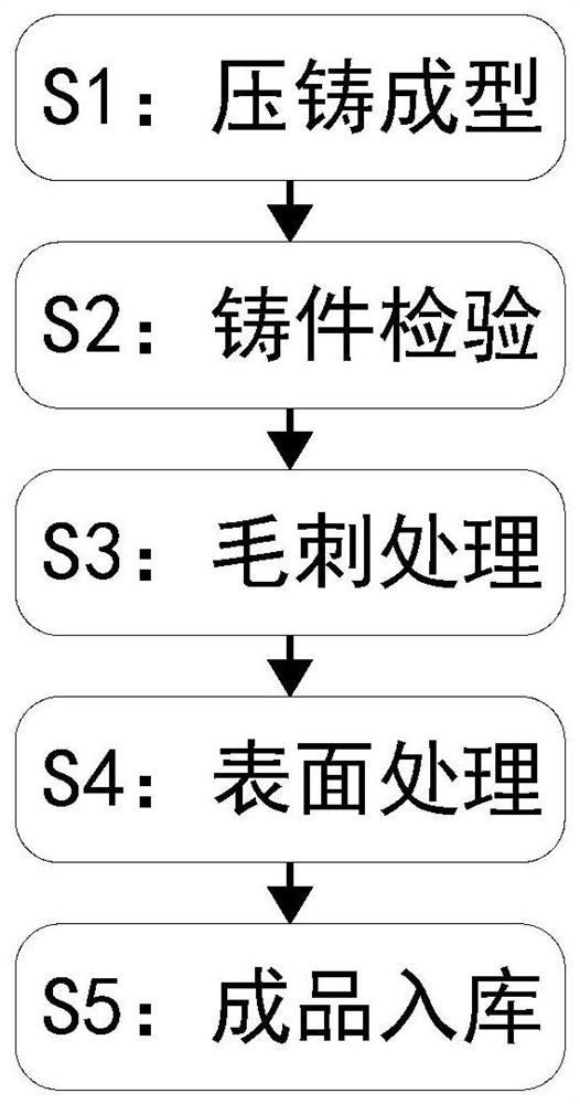
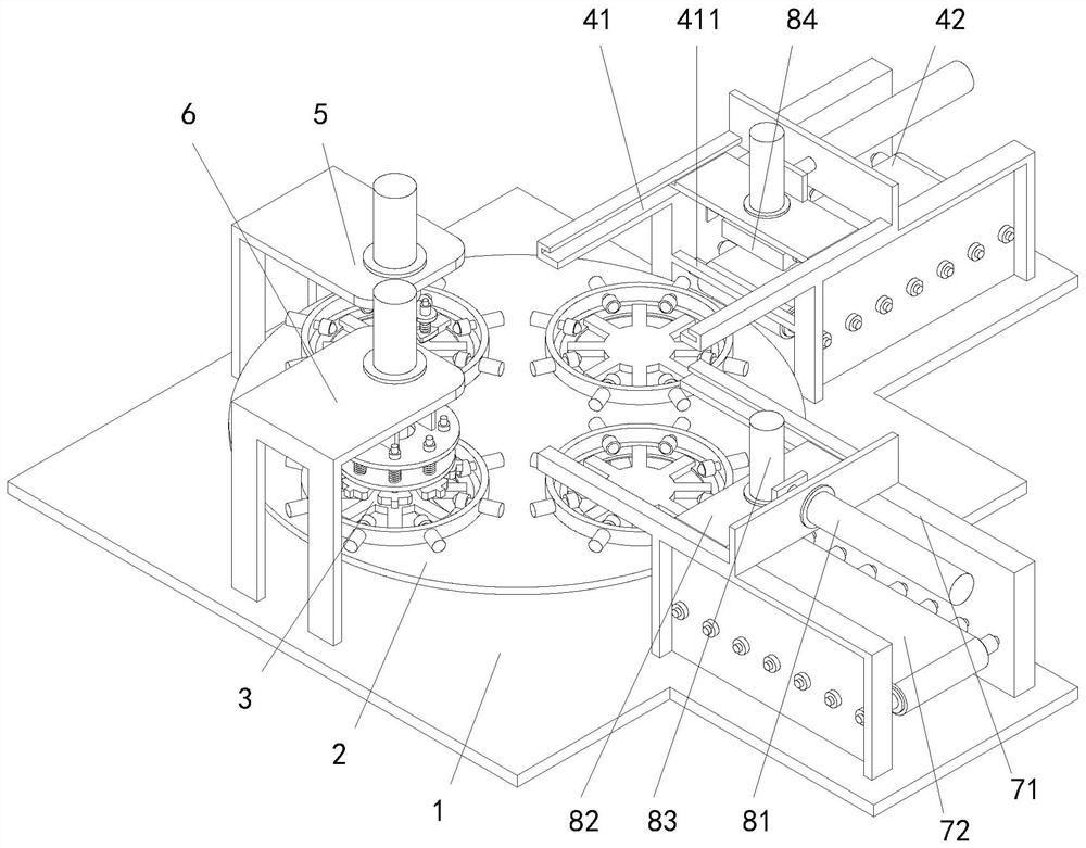
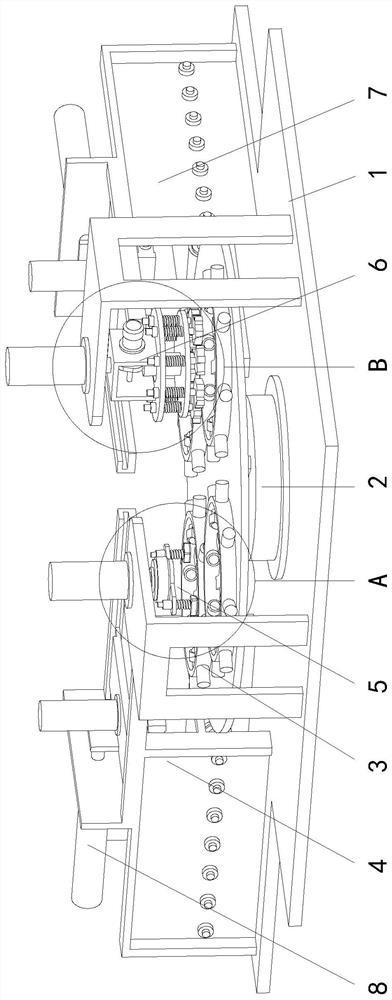
[0036] See attached Figure 1-11 As shown, a motor rotor die-casting manufacturing process, the manufacturing process specifically includes the following steps:

[0037] S1. Die-casting molding: inject the smelted metal raw material into the cavity of the die-casting mold to cool and form it;

[0038] S2. Casting inspection: inspect the die-cast motor rotor lamination castings, and select the motor rotor lamination castings that meet the inspection standards;

[0039] S3. Burr treatment: Deburring the groove walls of the selected motor rotor lamination casting...


PUM


Abstract

The invention relates to a motor rotor die-casting manufacturing process, in particular to a motor rotor casting groove wall cleaning device. The motor rotor die-casting manufacturing process comprises a base, an intermittent transposition mechanism, a clamping and positioning mechanism, a feeding mechanism, a shifting and positioning mechanism, a groove wall cleaning mechanism, a discharging mechanism and a grabbing and feeding mechanism. The device provided by the motor rotor die-casting manufacturing process is suitable for carrying out streamlined processing treatment on motor rotor laminations, the efficiency is greatly improved, the grinding quality uniformity is high, damage to the motor rotor laminations due to improper grinding can be avoided, the grinding quality is ensured, andthe size precision and the appearance attractiveness of the motor rotor laminations are maintained.

Description

technical field [0001] The invention relates to the technical field of motor component processing, and specifically proposes a motor rotor die-casting manufacturing process. Background technique [0002] The motor is composed of two parts, the rotor and the stator. It is used to realize the conversion of electrical energy and mechanical energy and mechanical energy and electrical energy. The motor rotor is the rotating part of the motor. The motor rotor can be divided into motor rotor and generator rotor. The motor rotor is mainly composed of iron core, rotor winding and rotating shaft. Since a thicker large iron core will cause greater eddy current damage and reduce the motor torque, the motor rotor is usually composed of several ferromagnetic conductor sheets. As a result, the eddy current loss can be significantly reduced, so the motor rotor widely adopts the laminated iron core structure; in order to adapt to mass production, the motor rotor laminates can be processed by...

Claims


Application Information

Patent Timeline
Patent Type & Authority Applications(China)
IPC IPC(8): B22D17/00B22D31/00B24B27/033B24B41/00H02K15/02
CPCB22D17/00B22D31/007B24B27/033B24B41/005H02K15/02
Inventor 李红梅李海波李锦余
Owner 威海立安精密铸造有限公司
Why Eureka
Try Eureka