Electrochemical hydrogenation upgrading device for bio-oil
A hydrogenation upgrading and bio-oil technology, applied in chemical instruments and methods, chemical/physical processes, chemical/physical/physicochemical processes, etc. Reactor and other problems, to achieve the effect of increasing the residence time, increasing the temperature parameters, and increasing the contact area
- Summary
- Abstract
- Description
- Claims
- Application Information
AI Technical Summary
Problems solved by technology
Method used
Image
Examples
Embodiment 1
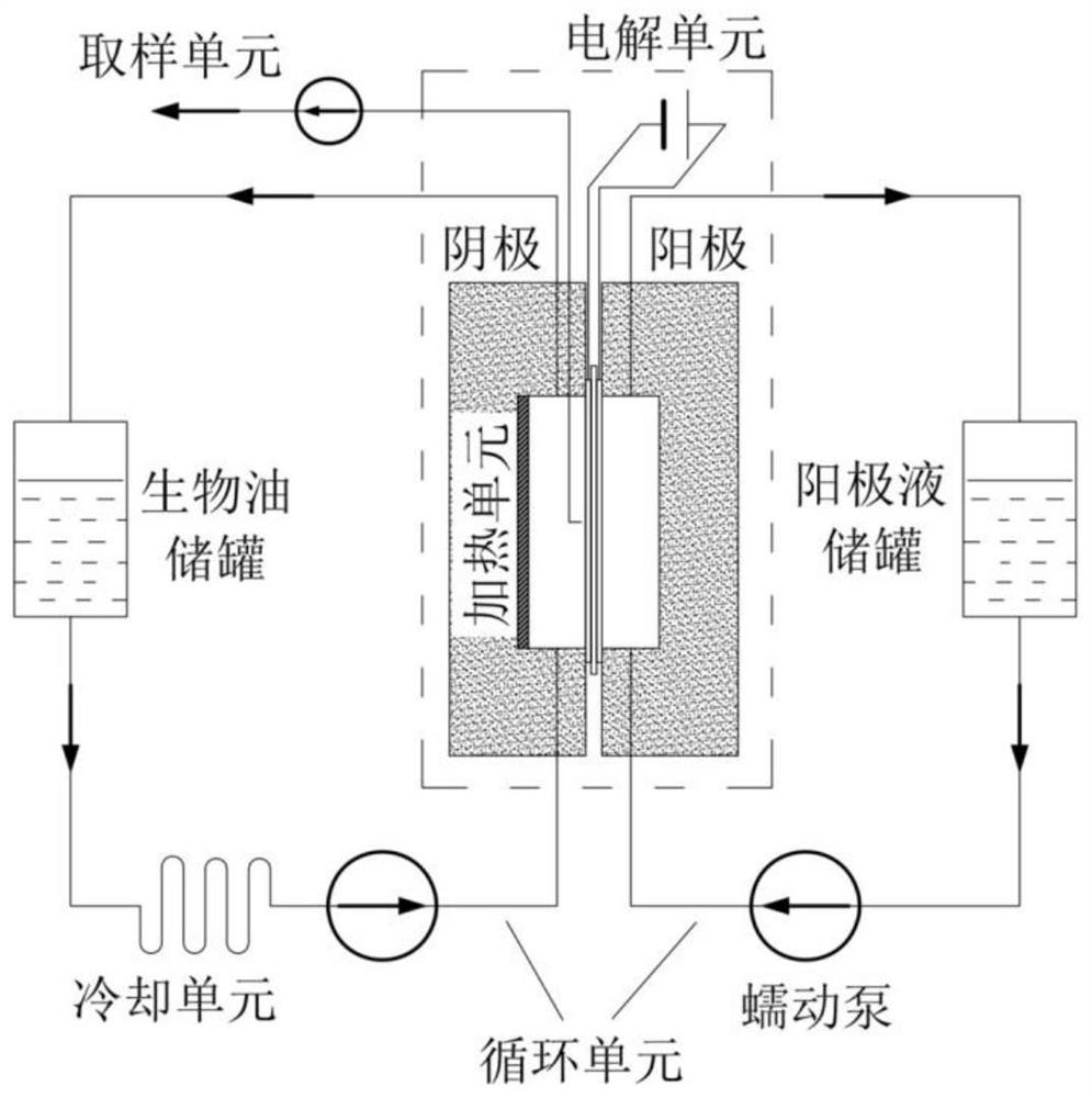
[0032] Such as figure 1 As shown, the embodiment of the present invention proposes a device for electrochemical hydrotreating and upgrading bio-oil, which includes an electrolysis unit, a circulation unit, a heating unit, a cooling unit and a sampling unit.
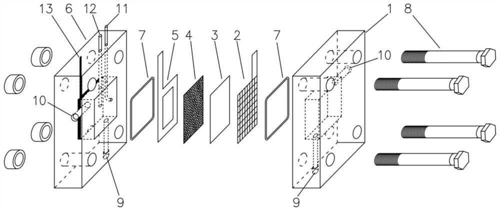
[0033] The electrolysis unit includes an anode chamber, an anode electrode, a proton exchange membrane, a catalytic electrode, a conductive ring, and a cathode chamber. Among them, the anode chamber and the cathode chamber are solid polytetrafluoroethylene blocks with square grooves, the grooves are the anode / catholyte flow chambers, the anode / catholyte inlets are located at the bottom of the groove, and the outlet is located at the top of the side of the groove , the inlet and outlet of the anode chamber and the cathode chamber are respectively located on both sides of the chamber, so that the inlet and outlet interfaces of the cathode and anode chambers will not interfere when connecting external pipes. The bottom of t...
Embodiment 2
[0045] Different from Example 1, a heating unit is used in this example to control the reaction temperature. The heating unit is composed of a cathode chamber heating resistance wire, a thermocouple, a temperature controller and a DC power supply. The resistance wire is laid on the back of the cathode chamber (that is, the resistance wire is arranged on the back of the groove). There are capillary sampling tubes and thermocouple sockets on the top of the cathode chamber, and the thermocouples are inserted into the reserved sockets of the cathode chamber. By controlling the reaction temperature in the cathode chamber, the bio-oil samples were subjected to constant current hydrogenation and upgrading under the temperature conditions of 30°C, 40°C, 50°C, 60°C, and 70°C, respectively. The hydrogenation yields of representative bio-oil compounds at different reaction temperatures are as follows: Figure 4 shown.
Embodiment 3
[0047] Different from Example 1, in this example, a sampling unit is used to realize online monitoring of the hydrogenation and upgrading process of the bio-oil sample. The sampling unit consists of a capillary sampling tube and a peristaltic pump. The sampling port is close to the surface of the catalytic electrode to realize online sampling of catholyte, which is transported and collected by a peristaltic pump, and then sent to analytical instruments, such as gas chromatography-mass spectrometer and ultraviolet fluorescence spectrometer, which can realize in-situ detection of reaction products. During operation, timing sample collection is realized by adjusting the flow rate of the peristaltic pump. The collected sample is immediately diluted with methanol to a concentration suitable for the analytical instrument, and then sent to the ultraviolet fluorescence spectrometer and gas chromatograph mass spectrometer for analysis. Through real-time monitoring, the degree of bio-oi...
PUM
 Abstract
Description
Claims
Application Information
 - R&D
- Intellectual Property
- Life Sciences
- Materials
- Tech Scout
- Unparalleled Data Quality
- Higher Quality Content
- 60% Fewer Hallucinations
Browse by: Latest US Patents, China's latest patents, Technical Efficacy Thesaurus, Application Domain, Technology Topic, Popular Technical Reports.
© 2025 PatSnap. All rights reserved.Legal|Privacy policy|Modern Slavery Act Transparency Statement|Sitemap|About US| Contact US: help@patsnap.com


