
Novel suspension type branch crusher

A suspension type, pulverizer technology, applied in agricultural machinery and implements, cutting equipment, applications, etc., can solve the problems of easy slippage of twigs, grinding of blades, etc., to avoid inconsistent speed, increase friction, and reduce costs.

Pending Publication Date: 2020-11-03
浙江长旭工贸有限公司
View PDF0 Cites 0 Cited by
  • Summary
  • Abstract
  • Description
  • Claims
  • Application Information

AI Technical Summary

Problems solved by technology

[0005] The purpose of the present invention is to provide a new type of hanging branch shredder, through the pressing plate with sawtooth, the branches are pressed more tightly and neatly, so as to avoid the wear and tear of the rotating knife shaft by the messy branches; and due to the existence of the sawtooth The friction can be increased to avoid the slipping of the thin branches, thus solving the problem that the thin branches are easy to slip away and the blades are grinded in the existing shredder

Method used


Image

  • Novel suspension type branch crusher
  • Novel suspension type branch crusher
  • Novel suspension type branch crusher

Examples


Embodiment 1

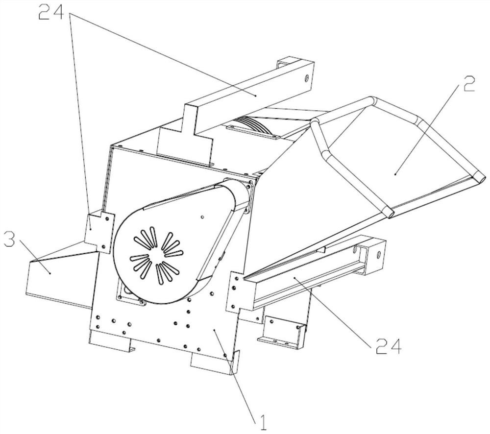
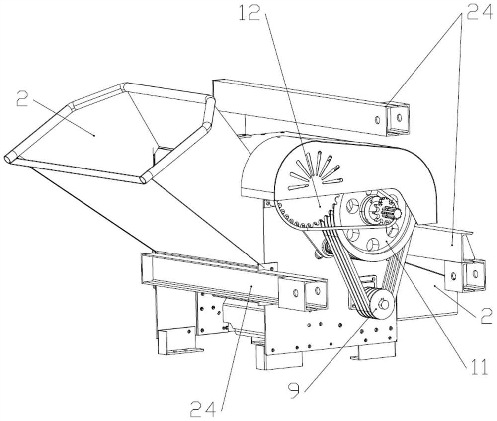
[0046] to combine Figure 1-Figure 4 , it can be seen that the new type of hanging type branch shredder includes a body 1, and one end of the body 1 is a feed end 2, and the other end of the body 1 is a discharge end 3. Wherein the feeding end 2 is an inclined funnel, so the feeding port of the feeding end 2 is relatively large, thereby facilitating feeding.

[0047] At the same time, the pulverizer also includes a cutting assembly, and the cutting assembly is arranged in the machine body 1 and is located between the feeding end 2 and the discharging end 3 . Therefore, in actual use, branches come in from the feed end 2, pass through the cutting assembly to be shredded, and then go out from the discharge end 3.

[0048] Wherein the length of the discharge end 3 is compared with the discharge end 3 of the reference document in the background technology, the length of the present invention is longer, that is, the length of a transition section is added instead of directly exiti...

Embodiment 2

[0074] Embodiment 2: This embodiment is basically the same as Embodiment 1, the difference is that: the front or rear end of the body 1 is provided with wheels, and the body 1 is provided with or externally connected with a driving source 2 that drives the wheels to rotate, and the body is rotated by the wheels. 1 move.

[0075] Wherein the driving source 2 can be a motor, thereby being arranged on the body 1; or the driving source 2 is a tricycle, a tractor, etc., and then pulls the body 1 to move through traction parts such as ropes.

[0076] Therefore, in actual use, the machine body 1 can be moved by driving the wheels to rotate through the driving source 2 . Simultaneously for comfort, thus can be provided with seat, armrest etc.


PUM


Abstract

The invention belongs to the technical field of crushers, and particularly relates to a novel suspension type branch crusher. The novel suspension type branch crusher comprises a machine body and a cutting assembly, wherein one end of the machine body is a feeding end, and the other end of the machine body is a discharging end; the cutting assembly is arranged in the machine body and located between the feeding end and the discharging end so as to be used for cutting up branches entering from the feeding end and discharging the cut-up branches out from the discharging end; the novel suspensiontype branch crusher further comprises a roller shaft, the roller shaft is rotationally arranged in the machine body and located between the feeding end and the cutting assembly, and the branches areconveyed to the cutting assembly through the roller shaft to be cut; and a plurality of pressing plates with sawteeth are arranged on the peripheral side of the roller shaft, and the branches are pressed through the pressing plates so that the branches can be compact and tidy. According to the novel suspension type branch crusher, by means of the pressing plates with the sawteeth, the branches arepressed to be more compact and tidy, so that the situation that a rotating cutter shaft is abraded by messy branches is avoided; and due to the existence of the sawteeth, the friction can be increased, so that thin branches are prevented from sliding away.

Description

technical field [0001] The invention belongs to the technical field of pulverizers, in particular to a novel suspended branch pulverizer. Background technique [0002] The pulverizer is a device that integrates slicing and crushing, and can cut branches and branches with a diameter of 1-20 cm. At the same time, the equipment can also be used for cutting fibrous stalk-like materials such as bamboo, thatch, corn stalks, and sorghum stalks. [0003] Since the existing pulverizers use manual feeding, the transportation structure is designed. For example, the patent number is 2018214411012, and the patent name is the invention patent of the branch straw pulverizer. This patent uses chain plates to realize automatic feeding. . [0004] However, there are problems in the actual operation of such equipment. First of all, the bottom surface of the chain plate and the surface of the feed plate are relatively smooth, so the friction is relatively small, so some thin branches will fol...

Claims


Application Information

Patent Timeline
Patent Type & Authority Applications(China)
IPC IPC(8): A01F29/02A01F29/10A01F29/14A01F29/09
CPCA01F29/02A01F29/09A01F29/10A01F29/14
Inventor 雷春柳童一宁朱一丹
Owner 浙江长旭工贸有限公司
Learn More