Boosting type wireless electric energy transmission coil and winding method of coil
A wireless energy transmission and step-up technology, applied in the direction of transformer/inductor coil/winding/connection, transformer/inductor parts, inductor/transformer/magnet manufacturing, etc., can solve the problems of wireless energy transmission limitations, etc., to achieve Strong anti-offset ability, enhanced magnetic field strength, and improved power density
- Summary
- Abstract
- Description
- Claims
- Application Information
AI Technical Summary
Problems solved by technology
Method used
Image
Examples
specific Embodiment 1
[0038] Specific embodiment 1: the coil winding method of the present invention, as figure 2shown. The transmitting coil is a single-layer coil, specifically, the single-layer coil includes a first lead head a1, a coil layer a2, and a first lead tail a3; the outermost coil of the coil layer a2 and the first lead end a1 is connected; the innermost circle of the coil layer a2 is connected to the first lead tail a3. The winding method is as follows: take a piece of wire, bend one end of the wire to form the first lead head a1, and then wind the wire behind the first lead head a1 on the same central axis plane; after winding enough turns, The coil layer a2 is formed; after enough turns are wound, the other end of the wire is bent in the innermost turn to form the first lead tail a3.
[0039] The coil at the receiving end is a double-layer coil, specifically, the double-layer coil includes a second lead head b1, a first coil layer b2, a cross-layer line segment b3, a second coil ...
specific Embodiment 2
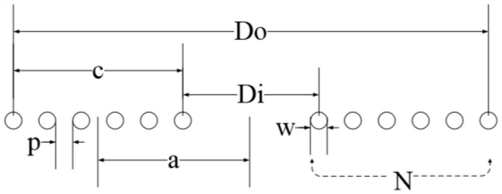
[0048] Specific embodiment 2, a boost type wireless power transmission coil according to the present invention is a planar spiral coil, such as Figure 5 Shown: including transmitter coil A1, receiver coil A2, lower magnetic isolation sheet A3 and upper magnetic isolation sheet A4. A cross-sectional view of a planar helical coil is shown in figure 2 As shown, its single-layer structural equation is:
[0049]
[0050] Determine the outer diameter D of the coil according to the working space and site of the coil o ;Determine the inner diameter D of the coil according to the required magnetic field formed by the coil i , and D i =D o -2N(w+p); Determine the total length l of the wire used in the coil according to the outer diameter, inner diameter and number of turns of the coil, and the width c of the coil portion, and the distance a from the middle of the coil width to the central axis, and Among them, p is the distance between each turn of the coil, w is the diam...
specific Embodiment 3
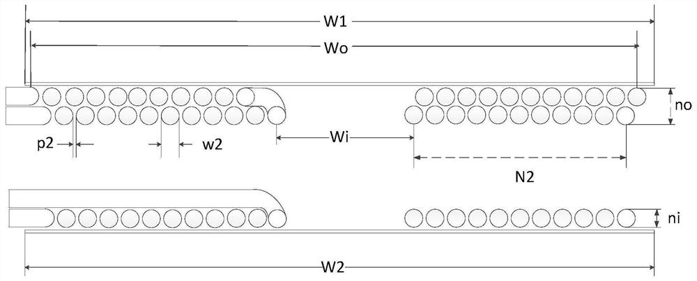
[0052] Specific embodiment 3, a boost type wireless power transmission coil according to the present invention is a planar rounded rectangular coil, such as Figure 6 Shown: including transmitter coil B1, receiver coil B2, lower magnetic isolation piece B3 and upper magnetic isolation piece B4. The cross-sectional view of the plane rounded rectangular coil is as follows image 3 As shown, the outer length L of the coil is determined according to the working space and site of the coil o and the outer width of the coil W o ; Determine the inner length L of the coil according to the required magnetic field formed by the coil i and the inner width of the coil W i , and L i = L o -2N(w+p),W i =W o -2N(w+p); determine the total length l of the wire used by the coil according to the outer length, outer width and number of turns of the coil, and l=2N(L o +W o )-4N(N-1)(w+p); Among them, p is the distance between the coils of each turn, w is the diameter of the wire, and N is ...
PUM
| Property | Measurement | Unit |
|---|---|---|
| diameter | aaaaa | aaaaa |
| diameter | aaaaa | aaaaa |
| width | aaaaa | aaaaa |
Abstract
Description
Claims
Application Information
 - Generate Ideas
- Intellectual Property
- Life Sciences
- Materials
- Tech Scout
- Unparalleled Data Quality
- Higher Quality Content
- 60% Fewer Hallucinations
Browse by: Latest US Patents, China's latest patents, Technical Efficacy Thesaurus, Application Domain, Technology Topic, Popular Technical Reports.
© 2025 PatSnap. All rights reserved.Legal|Privacy policy|Modern Slavery Act Transparency Statement|Sitemap|About US| Contact US: help@patsnap.com


