Magnetic core for high-frequency high-impedance ignition coil

An ignition coil, high impedance technology, applied in the direction of transformer/inductor magnetic core, inductor, inductive energy storage device, etc., can solve problems such as the stability of the magnetic core affecting the ignition coil, unstable connection, etc., to improve the stability , the effect of improving the connection strength

Active Publication Date: 2020-10-30
ANHUI HUALIN MAGNETIC TECH
View PDF7 Cites 0 Cited by
  • Summary
  • Abstract
  • Description
  • Claims
  • Application Information

AI Technical Summary

Problems solved by technology

[0002] In the related technology, the ignition coil is an important executive component that ignites the air and fuel mixture in the engine cylinder to provide ignition energy. The ignition coil core is the core part of the ignition coil. The patent application number 201420439215.9 discloses a high-energy ignition coil core , but because the cylinder and the upper end cover are connected through the terminal, the connection between the cylinder and the upper end cover is not stable, which affects the stability of the magnetic core operation of the ignition coil

Method used


Image

  • Magnetic core for high-frequency high-impedance ignition coil
  • Magnetic core for high-frequency high-impedance ignition coil
  • Magnetic core for high-frequency high-impedance ignition coil

Examples


Embodiment 1

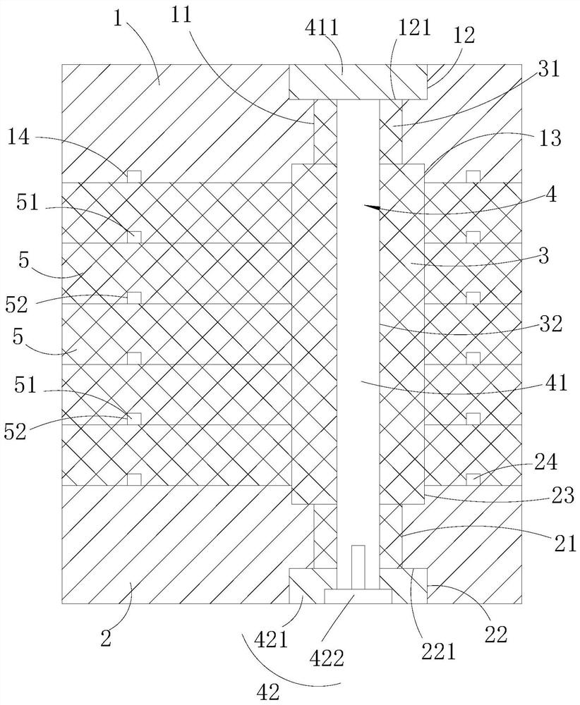
[0038] Such as Figure 1 to Figure 3 As shown, the present invention provides a magnetic core for a high-frequency high-impedance ignition coil, including: a first end cap 1 and a second end cap 2 arranged at intervals, and the first end cap 1 is provided with a non-circular The first positioning through hole 11, the second end cover 2 is provided with a non-circular second positioning through hole 21; the magnetic post 3, the magnetic post 3 is arranged on the first end cover 1 and the second end cover 1 Between the two end caps 2, the two ends of the positioning column are provided with positioning parts 31, and the two positioning parts 31 extend into the first positioning through hole 11 and the second positioning through hole correspondingly. 21, and a non-circular perforation 32 is provided in the magnetic column 3; a positioning member 4, the positioning member 4 includes a positioning rod 41 and a fixing part 42, and one end of the positioning rod 41 is provided with a...

Embodiment 2

[0041] The difference between this embodiment and the foregoing embodiments is that;

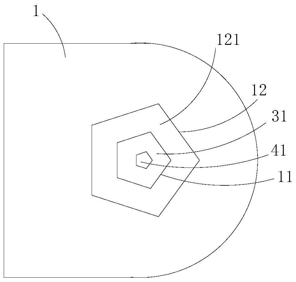
[0042] Such as Figure 1 to Figure 3As shown, in some embodiments of the present invention, the side of the first end cap 1 away from the second end cap 2 is provided with a first limiting groove 12 communicating with the first positioning through hole 11 , the first limiting groove 12 is non-circular, and the bottom surface of the first limiting groove 12 defines a first limiting table 121 , and the positioning head 411 is embedded in the first limiting groove 12 Inside, and the positioning head 411 stops against the first limiting platform 121 . In this way, the positioning head 411 is prevented from being exposed to the outside, and the flatness of the first end cover 1 is ensured, which is convenient for installation and fixing.

[0043] In some embodiments of the present invention, the side of the second end cap 2 away from the first end cap 1 is provided with a second limiting groove...

Embodiment 3

[0048] The difference between this embodiment and the foregoing embodiments is that;

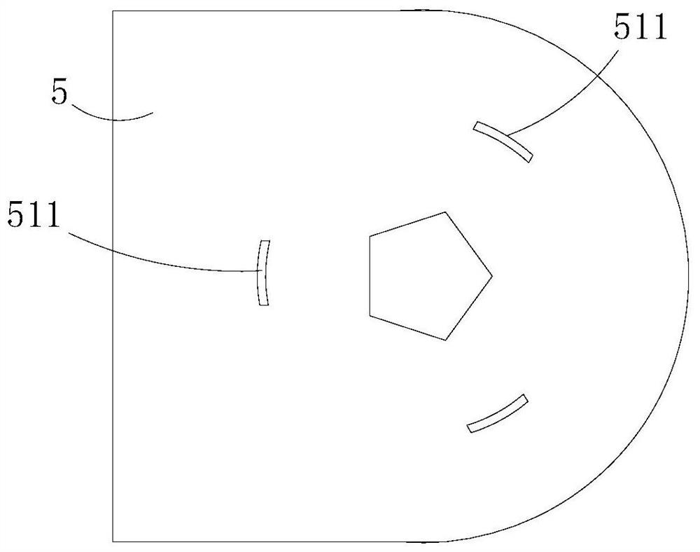
[0049] Such as Figure 1 to Figure 3 As shown, in some embodiments of the present invention, one side of each magnetic sheet 5 is provided with a foolproof portion 51, and the other side of each magnetic sheet 5 is provided with a foolproof slot 52, and each magnetic sheet 5 is provided with a foolproof groove 52. The fool-proof portions 51 of each piece 5 extend into the fool-proof slots 52 of adjacent magnetic pieces 5 . In this way, the relative rotation of two adjacent magnetic pieces 5 and the phenomenon of reverse installation can be avoided.

[0050] In some embodiments of the present invention, the fool-proof portion 51 includes a plurality of fool-proof protrusions 511 arranged at intervals along the circumference of the magnetic sheet 5 , and the fool-proof groove 52 includes A plurality of fool-proof grooves arranged at intervals in the circumferential direction.

[0051] In so...


PUM


Abstract

The invention provides a magnetic core for a high-frequency high-impedance ignition coil, which is characterized in that a first end cover is provided with a non-circular first positioning through hole, and a second end cover is provided with a non-circular second positioning through hole; positioning parts are arranged at the two ends of the positioning column, the positioning rod is arranged inthe through hole in a penetrating mode, the positioning head abuts against the first end cover, the fixing part abuts against the second end cover, and the fixing part is connected with the other endof the positioning rod; the two positioning parts of the magnetic column respectively extend into the first positioning through hole and the second positioning through hole; the positioning connectionamong the magnetic column, the first end cover and the second end cover is realized; a positioning rod of the positioning piece is arranged in the through hole of the magnetic column in a penetratingmanner; and the positioning head of the positioning rod is propped against the first end cover, and the other end of the positioning rod is propped against the second end cover through the fixing part, so that the magnetic column, the first end cover and the second end cover are connected through the positioning piece, the connection strength among all parts of the magnetic core is improved, andthe purpose of improving the operation stability of the magnetic core is achieved.

Description

technical field [0001] The invention relates to the technical field of magnetic cores for ignition coils, in particular to a magnetic core for high-frequency high-impedance ignition coils. Background technique [0002] In the related technology, the ignition coil is an important executive component that ignites the air and fuel mixture in the engine cylinder to provide ignition energy. The ignition coil core is the core part of the ignition coil. The patent application number 201420439215.9 discloses a high-energy ignition coil core , but because the cylinder and the upper end cap are connected by terminals, the connection between the cylinder and the upper end cap is not stable, thus affecting the stability of the magnetic core operation of the ignition coil. [0003] Therefore, it is necessary to develop a high-frequency high-impedance ignition coil magnetic core to solve the above technical problems. Contents of the invention [0004] The purpose of the present inventi...

Claims


Application Information

Patent Timeline
Patent Type & Authority Applications(China)
IPC IPC(8): H01F27/26H01F38/12F02P3/02
CPCH01F27/263H01F38/12F02P3/02
Inventor 沈宏江蔡忠贤张学舟
Owner ANHUI HUALIN MAGNETIC TECH
Why Eureka
Try Eureka