Flat ultra-thin heat pipe with thermal superconductivity

A thermal superconducting, ultra-thin technology, applied in indirect heat exchangers, lighting and heating equipment, etc., can solve the problems of low yield, unstable thermal conductivity, and low thermal conductivity

Pending Publication Date: 2020-10-30
遵义迪生电子科技有限公司
View PDF2 Cites 0 Cited by
  • Summary
  • Abstract
  • Description
  • Claims
  • Application Information

AI Technical Summary

Problems solved by technology

[0007] The purpose of the present invention is to solve the problems existing in the prior art, such as low heat conduction efficiency, unstable heat conduction characteristics, and low yield rate of the heat pipe due to process and structure limitations, so it provides a flat and ultra-thin heat pipe with thermal superconductivity. Heat pipe, so that the ultra-thin heat pipe has excellent thermal conductivity, and it is easy to mass produce and has a high yield

Method used


Image

  • Flat ultra-thin heat pipe with thermal superconductivity
  • Flat ultra-thin heat pipe with thermal superconductivity
  • Flat ultra-thin heat pipe with thermal superconductivity

Examples


Embodiment 1

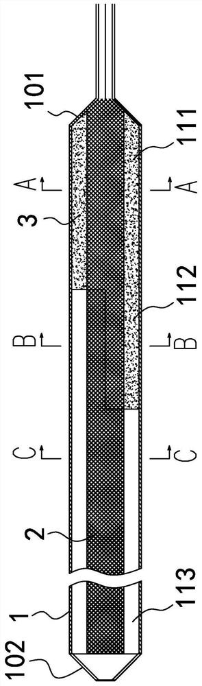
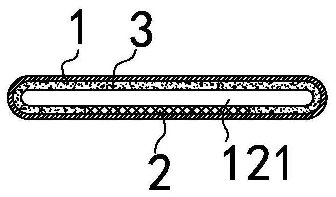
[0052] as attached figure 1 to attach Figure 10 As shown, Embodiment 1 of the present invention proposes a flat and ultra-thin heat pipe with thermal superconductivity, including a tube body 1, one end of the tube body 1 is an evaporation end 101, and the other end is a condensation end 102, and the tube body 1 There is a sealed hollow flat space in the hollow flat space, and the working liquid is encapsulated in the hollow flat space. The first capillary structure 2 and the second capillary structure 3 are arranged in the hollow flat space, and the first capillary structure 2 is copper wire bundle or Copper wire braid, the second capillary structure 3 is a sintered copper powder, and the remaining space in the hollow flat space except the first capillary structure 2 and the second capillary structure 3 forms a steam space, wherein:

[0053] The steam flow path of the pipe body 1 extending from the evaporation end 101 to the condensation end 102 is sequentially provided wit...

Embodiment 2

[0062] as attached Figure 10 As shown, Embodiment 2 of the present invention proposes a flat and ultra-thin heat pipe with thermal superconductivity, including a tube body 1, one end of the tube body 1 is an evaporation end 101, and the other end is a condensation end 102, and the tube body 1 There is a sealed hollow flat space in the hollow flat space, and the working liquid is encapsulated in the hollow flat space. The first capillary structure 2 and the second capillary structure 3 are arranged in the hollow flat space, and the first capillary structure 2 is copper wire bundle or Copper wire braid, the second capillary structure 3 is a sintered copper powder, and the remaining space in the hollow flat space except the first capillary structure 2 and the second capillary structure 3 forms a steam space, wherein:

[0063] The steam flow path extending from the tube body 1 along the evaporation end 101 to the condensation end 102 is sequentially defined as a full section 111 ...


PUM

PropertyMeasurementUnit
Thicknessaaaaaaaaaa
Wall thicknessaaaaaaaaaa
Thermal resistanceaaaaaaaaaa

Abstract

The invention discloses a flat ultra-thin heat pipe with thermal superconductivity. The flat ultra-thin heat pipe with thermal superconductivity includes a tube body with a sealed hollow flat space; the two ends of the tube body are an evaporation end and a condensation end; a full section, a transition section and an empty section are arranged in sequence along the steam flow path; the steam space from the full section to the transition section and then to the empty section increases gradually; a first capillary structure and a second capillary structure are arranged in the tube body; the first capillary structure extends from the evaporation end to the condensation end of the inner wall of the tube body; and the second capillary structure is attached to the inner wall of the tube body along the extension path of the full section to form a closed loop, or extends from the second capillary structure to the transition section. The flat ultra-thin heat pipe with thermal superconductivityadopts the capillary structure combination of powder sintering with good characteristics and copper wire bundle or copper wire braided fabric, so that the ultra-thin heat pipe has very good thermal superconductivity on the mixed capillary structure; the steam space is large, and the horizontal and inclined best capillary water flow can be obtained; and the flat ultra-thin heat pipe with thermal superconductivity cannot be peel off during bending and flattening, has a high yield during production, and can be applied to large-scale production.

Description

technical field [0001] The invention relates to the technical field of flat heat pipes, in particular to a flat ultra-thin heat pipe with thermal superconductivity. The heat pipe is mainly used in CPU cooling modules in ultra-thin notebooks, and can also be used in narrow spaces as heat conduction elements. Background technique [0002] A heat pipe is a heat-conducting element that uses the principle of heat conduction and a phase-change medium to achieve rapid heat transfer properties. Through the heat pipe, the heat of the heating object is quickly transferred to the outside of the heat source. Its thermal conductivity exceeds that of any known metal, and has been widely used. In electronic components with large heat generation. When the heat pipe is working, the low-boiling-point working medium filled in the tube body absorbs the heat generated by the heating electronic components in the evaporation part and then evaporates and vaporizes. The steam moves to the condensati...

Claims


Application Information

Patent Timeline
IPC IPC(8): F28D15/04
CPCF28D15/046
Inventor 叶元璋
Owner 遵义迪生电子科技有限公司
Why Eureka
Try Eureka