Vertical ladle for vacuum suction and injection of liquid rare earth metal

A rare earth metal, vacuum imbibition technology, applied in the direction of electrolysis process, electrolysis components, etc., can solve the problems of complexity, reduced output of electrolyzers, large equipment, etc.

Pending Publication Date: 2020-10-30
包头市金为达稀土材料有限公司
View PDF0 Cites 0 Cited by
  • Summary
  • Abstract
  • Description
  • Claims
  • Application Information

AI Technical Summary

Problems solved by technology

[0002] At present, the equipment that uses vacuum suction to take the molten metal out of the electrolytic cell, such as the aluminum outlet bag, is suitable for the production of metal aluminum, magnesium, etc. by electrolysis, but it is not suitable for the production of rare earths by electrolysis because of the large size, complexity and defects of electrolyte slagging. Metal, the way to discharge rare earth metals from the electrolytic cell is generally to use manual or mechanical scoops and spoons to take out the equipment and methods. When taking out the operation, the electrolytic cell needs to be powered off, which has the disadvantage of reducing production. Furthermore, the liquid rare earth metals taken out each time The amount is small, and there are shortcomings of composition differences between pools and between times. The aluminum (magnesium) type table bag has the disadvantage of slagging, good heat preservation effect, and is suitable for the production of liquid rare earth metal electrolytic cells. The equipment for vacuum pumping liquid rare earth metals can not only increase the output of electrolytic cells, but also reduce labor intensity. Improve the quality of rare earth metals

Method used


Image

  • Vertical ladle for vacuum suction and injection of liquid rare earth metal
  • Vertical ladle for vacuum suction and injection of liquid rare earth metal
  • Vertical ladle for vacuum suction and injection of liquid rare earth metal

Examples


Embodiment 1

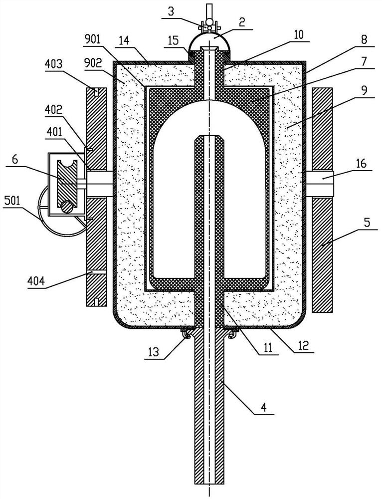
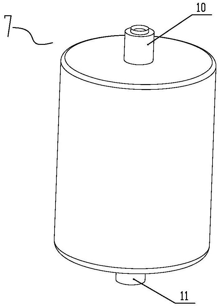
[0036] Embodiment 1: When the present invention is used in the production of liquid rare earth metals by electrolysis, the components mentioned above are prepared before operation and connected and assembled, and the arm frame of the external plug-in vehicle is connected and fixed with the package body connector 5 , fix the externally equipped vacuum pump with an air pumping capacity of 0.5 liters per second on the enclosure connector 5, and connect the externally equipped vacuum hose to the vacuum line interface 311, and the externally equipped compressed air source tube and the booster Air interface 309 is connected well, and the total height of the present invention is 1780mm, and the inner diameter of liquid suction pipe 4 is 30mm, and the inner cavity volume of liquid storage liner 7 is 65 liters, and the total height of inner cavity is 0.6 meter. Cover the liquid outlet sealing cap 2, and press the hollow swing rod 303 with wedge pin 305 to form a seal between the liquid ...


PUM


Abstract

The invention provides a vertical ladle for vacuum suction and injection of liquid rare earth metal. The vertical ladle comprises a molten metal containing ladle body, a liquid outlet sealing cap, a sealing cap gas circuit opening and closing assembly, a liquid suction pipe, a ladle body connecting piece and a tilting component. According to the vertical ladle, the gas pressure in the ladle is adjustable, the situation that electrolyte cannot enter a liquid storage inner container in the pipe inserting process of the liquid suction pipe is prevented, metal, the electrolyte and the like can bethoroughly poured out of the liquid storage inner container in an upside down pouring mode, the defect that the electrolyte and slag are left in the ladle is overcome, the temperature drop of molten metal in unit time can be greatly reduced through a heat preservation layer structure, the requirement that liquid metal is extracted to the same ladle from different electrolytic tanks one by one andcollected together for pouring (ingot casting) is met, and after the liquid rare earth metal in the tanks is extracted and poured, the components are mixed evenly.

Description

technical field [0001] The invention belongs to the field of metal smelting, in particular to a vertical table bag for vacuum suction and injection of liquid rare earth metals. Background technique [0002] At present, the equipment that uses vacuum suction to take the molten metal out of the electrolytic cell, such as the aluminum outlet bag, is suitable for the production of metal aluminum, magnesium, etc. by electrolysis, but it is not suitable for the production of rare earths by electrolysis because of the large size, complexity and defects of electrolyte slagging. Metal, the way to discharge rare earth metals from the electrolytic cell is generally to use manual or mechanical scoops and spoons to take out the equipment and methods. When taking out the operation, the electrolytic cell needs to be powered off, which has the disadvantage of reducing production. Furthermore, the liquid rare earth metals taken out each time The amount is small, and there are shortcomings of...

Claims


Application Information

Patent Timeline
IPC IPC(8): C25C7/06C25C3/34
CPCC25C3/34C25C7/06
Inventor 王振峰张山虎
Owner 包头市金为达稀土材料有限公司
Why Eureka
Try Eureka