Plastic powder cooling conveyor

A technology for cooling conveyors and conveyors, which is applied in the direction of conveyors, conveyor objects, transportation and packaging, etc., and can solve problems such as waste, inconvenience for users to maintain and dredge, and affect production efficiency

Inactive Publication Date: 2020-10-30
张梅琼
View PDF0 Cites 1 Cited by
  • Summary
  • Abstract
  • Description
  • Claims
  • Application Information

AI Technical Summary

Problems solved by technology

[0002] With the development of society, the application range of plastics is more and more extensive, and can be used in the fields of pesticides, food and daily chemicals. When plastics are recycled and processed, they need to be crushed into powders for processing. Powdered plastics need When conveying on an unprotected conveyor, it will cause the raw material to be unstable during the conveying process, resulting in a certain amount of waste, polluting the air, and causing injury to the workers, and the plastic powder conveying mechanism is easy to use when it is in use. The blockage in the pipeline will affect the subsequent material delivery, and it is not convenient for the user to maintain and dredge, which affects the production efficiency and brings a lot of inconvenience to the user. Moreover, after the plastic is recycled and processed, the plastic powder itself High heat will affect the work of the next process

Method used


Image

  • Plastic powder cooling conveyor
  • Plastic powder cooling conveyor
  • Plastic powder cooling conveyor

Examples


Embodiment

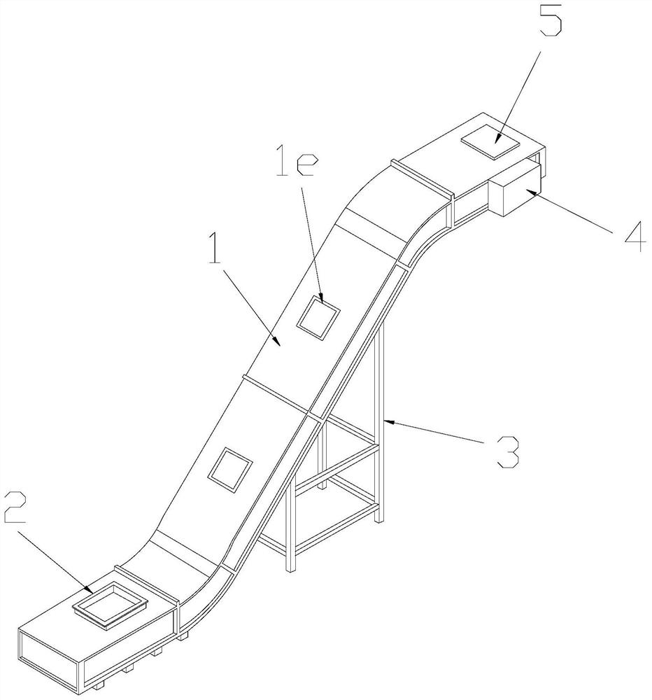
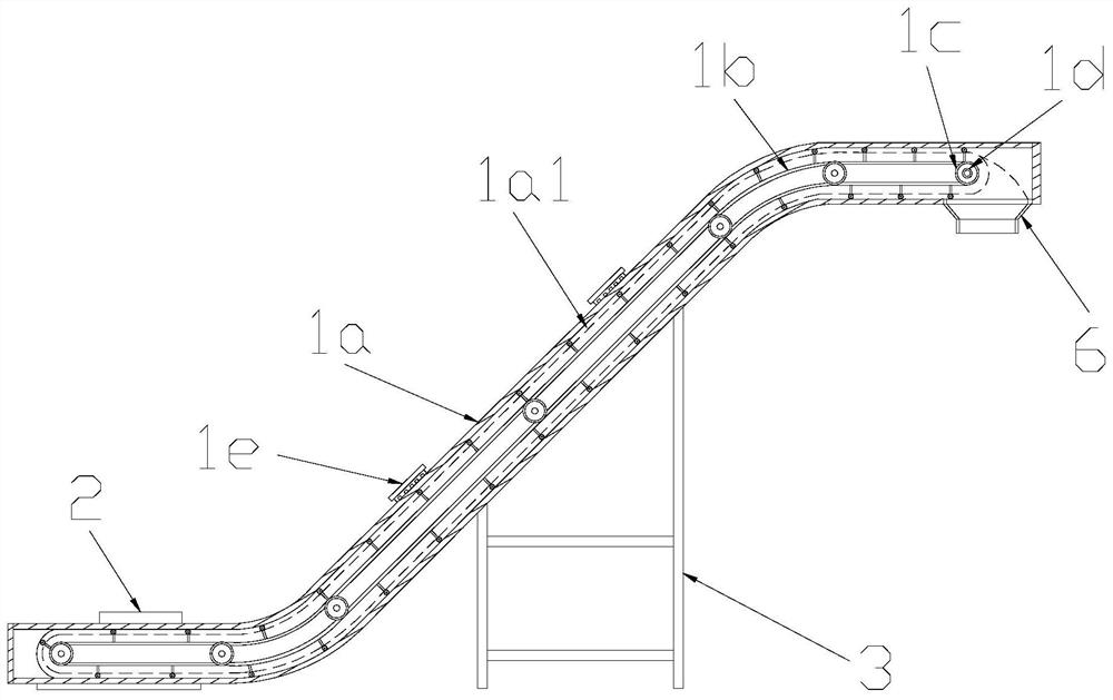
[0026] see Figure 1-Figure 4 , the present invention provides a plastic powder cooling conveyor, the structure of which includes a powder conveyor 1, a feed hopper 2, a support frame 3, a drive motor 4, an inspection cover 5, and a hopper 6. The bottom of the powder conveyor 1 A support frame 3 is provided below, and the powder conveyor 1 and the support frame 3 are flexibly connected. One end of the powder conveyor 1 is provided with a feed hopper 2, and the powder conveyor 1 and the feed hopper 2 are An integrated structure, the other end of the powder conveyor 1 is provided with an inspection cover 5 and a discharge hopper 6 respectively, and the inspection cover 5 and the discharge hopper 6 are connected to the powder conveyor 1. The powder conveyor 1. A driving motor 4 is installed on the surface of the other end;

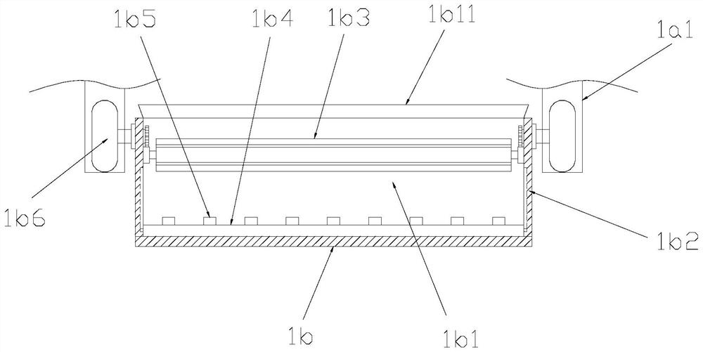
[0027] The powder conveyor 1 is composed of a body 1a, a conveyor belt 1b, a driving roller 1c, a rotating shaft 1d, and a ventilation cover 1e. The body 1a...


PUM


Abstract

The invention discloses a plastic powder cooling conveyor. The plastic powder cooling conveyor structurally comprises a powder conveyor body, a feeding hopper, a supporting frame, a driving motor, anaccess cover and a discharging hopper, the powder conveyor body disperses and pushes plastic powder through a pushing partition plate, and therefore the heat dissipation effect and the plastic powderdispersion effect can be achieved; the powder conveyor utilizes the positioning sliding rails to hang the climbing wheels, the situation that the conveying belt sinks inwards and conveying is affectedis avoided, the plastic powder is leveled through the leveling mechanism, the situation that the plastic powder drifts around due to the influence of a little air flow is avoided, and the powder is flattened through the sweeping rods; heat of plastic powder can be rapidly cooled, the situation that the next procedure is influenced by the heat of the plastic powder is avoided, the plastic powder can be flexibly pushed to be discharged by shaking a soft plate, a partition plate is pushed to clean the inner wall of the powder conveyor through soft rubber strips, and the situation that long-timeaccumulation of the inner wall of the powder conveyor influences pushing of the partition plate to slide is avoided.

Description

technical field [0001] The invention relates to the field of plastic processing, in particular to a plastic powder cooling conveyor. Background technique [0002] With the development of society, the application range of plastics is more and more extensive, and can be used in the fields of pesticides, food and daily chemicals. When plastics are recycled and processed, they need to be crushed into powders for processing. Powdered plastics need When conveying on an unprotected conveyor, it will cause the raw material to be unstable during the conveying process, resulting in a certain amount of waste, polluting the air, and causing injury to the workers, and the plastic powder conveying mechanism is easy to use when it is in use. The blockage in the pipeline will affect the subsequent material delivery, and it is not convenient for the user to maintain and dredge, which affects the production efficiency and brings a lot of inconvenience to the user. Moreover, after the plastic ...

Claims


Application Information

Patent Timeline
Patent Type & Authority Applications(China)
IPC IPC(8): B65G19/14B65G21/22B65G21/20B65G45/14B65G47/34
CPCB65G19/14B65G21/2063B65G21/22B65G45/14B65G47/34B65G2201/04
Inventor 张梅琼
Owner 张梅琼
Why Eureka
Try Eureka