Eureka AIR delivers breakthrough ideas for toughest innovation challenges, trusted by R&D personnel around the world.

Cleaning method used for spinning machine

A spinning machine and cleaning technology, applied in textiles and papermaking, etc., can solve the problems of manual cleaning of textile machines, and achieve the effect of saving manual operation time and easy and fast operation.

Inactive Publication Date: 2017-12-19
余庆县鸿祥棉纺有限责任公司
View PDF8 Cites 2 Cited by
  • Summary
  • Abstract
  • Description
  • Claims
  • Application Information

AI Technical Summary

Problems solved by technology

[0004] The present invention intends to provide a cleaning method for spinning machines to solve the current problem of manual cleaning of textile machines

Method used


Image

  • Cleaning method used for spinning machine
  • Cleaning method used for spinning machine

Examples


Embodiment Construction

[0025] The present invention will be described in further detail below by means of specific embodiments:

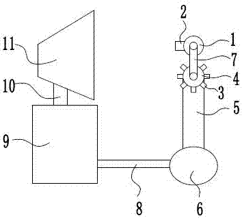
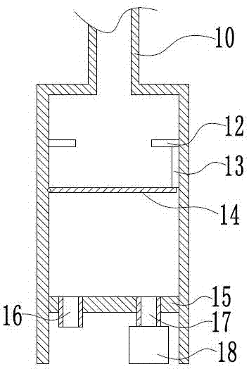
[0026] The reference signs in the accompanying drawings of the description include: rotating sleeve 1, dial block 2, push switch 3, nozzle 4, water spray pipe 5, water pump 6, guide strip 7, connecting strip 8, collection box 9, connecting pipe 10, Vacuum cleaner 11, contact switch 12, lifting rod 13, turnover plate 14, base plate 15, first discharge pipe 16, second discharge pipe 17, vacuum pump 18.

[0027] like figure 1 As shown, the spinning cleaning device includes a toggle device connected to the stator and rotates with the stator, and a cleaning head that is opened by the toggle device and sprays water to the stator. The toggle device includes a rotating sleeve 1 sleeved on the stator and rotates together with the stator, and a shifting block 2 arranged on the rotating sleeve 1 integrally formed with the rotating sleeve 1 and protruding radially outward. The clea...


PUM


Abstract

The invention belongs to the field of textile manufacturing machines, and discloses a cleaning method used for a spinning machine. The method comprises the steps that firstly, a toggling device is installed on a stator, and a vacuum pump and a water pump are started; secondly, the spinning machine is started, the toggling device rotates along with the stator and squeezes a cleaning head, the cleaning head receives the water from the water pump and sprays the water to the stator, and short fibers on the stator is impacted through the cleaning head and leaves from the stator; thirdly, the short fibers are drawn in a suction machine through the negative pressure generated by the vacuum pump and conveyed to a collection box.

Description

technical field [0001] The invention relates to the field of textile machinery, in particular to a cleaning method for a spinning machine. Background technique [0002] In the textile industry, many plant fibers are twisted together by a loom and spun into threads or yarns, which can be used to weave cloth. The textile machine includes a stator for spinning and passing the cotton thread. The stator can rotate. During the rotation of the stator, a large amount of short fibers are aggregated into a loose cotton thread, and then the cotton thread is pulled out little by little and twisted into a fine and dense fabric. cotton thread. After the textile machine has been used for a period of time, some short fibers will be wound on the stator, and when these short fibers accumulate to a certain thickness, it will hinder the rotation of the stator, thereby affecting the spinning speed of the cotton thread, so it is necessary to regularly check the short fibers on the stator. Fiber...

Claims


Application Information

Patent Timeline
IPC IPC(8): D01H11/00
CPCD01H11/005
Inventor 付兴国毛国权谈小年
Owner 余庆县鸿祥棉纺有限责任公司
Why Eureka
Eureka Blog
Learn More