
Conveying type electroplating machine

A conveying and mechanical technology, applied in the direction of abrasive jetting machine tools, used abrasive processing devices, explosion generating devices, etc., can solve the problem that abrasive particles cannot be ejected from the nozzle, affect metal sandblasting treatment, and unevenness of metal surface question

Inactive Publication Date: 2020-10-30
临漳县万盈贸易有限公司
View PDF6 Cites 0 Cited by
  • Summary
  • Abstract
  • Description
  • Claims
  • Application Information

AI Technical Summary

Problems solved by technology

[0002] In order to improve the wear resistance of the metal surface, etc., a layer of metal film is attached to the metal surface by electrolysis to prevent metal oxidation. The ejected abrasive impacts the metal surface, making the metal surface uneven, so that the metal film is fully attached to the metal surface; in the prior art, when the sandblasting machine blasts the metal surface, in order to strengthen the intensity of the spray beam, the diameter of the nozzle is smaller. Small, increase the pressure of the spray material, the size of the abrasive particles formed by the abrasive in the process of processing is different, and some abrasive particles are transported to the nozzle under the push of compressed air, so that the large abrasive particles cannot be ejected from the nozzle. The small hole of the nozzle is blocked, which affects the normal metal blasting treatment

Method used


Image

  • Conveying type electroplating machine
  • Conveying type electroplating machine
  • Conveying type electroplating machine

Examples


Embodiment 1

[0027] as attached figure 1 to attach Figure 5 Shown:

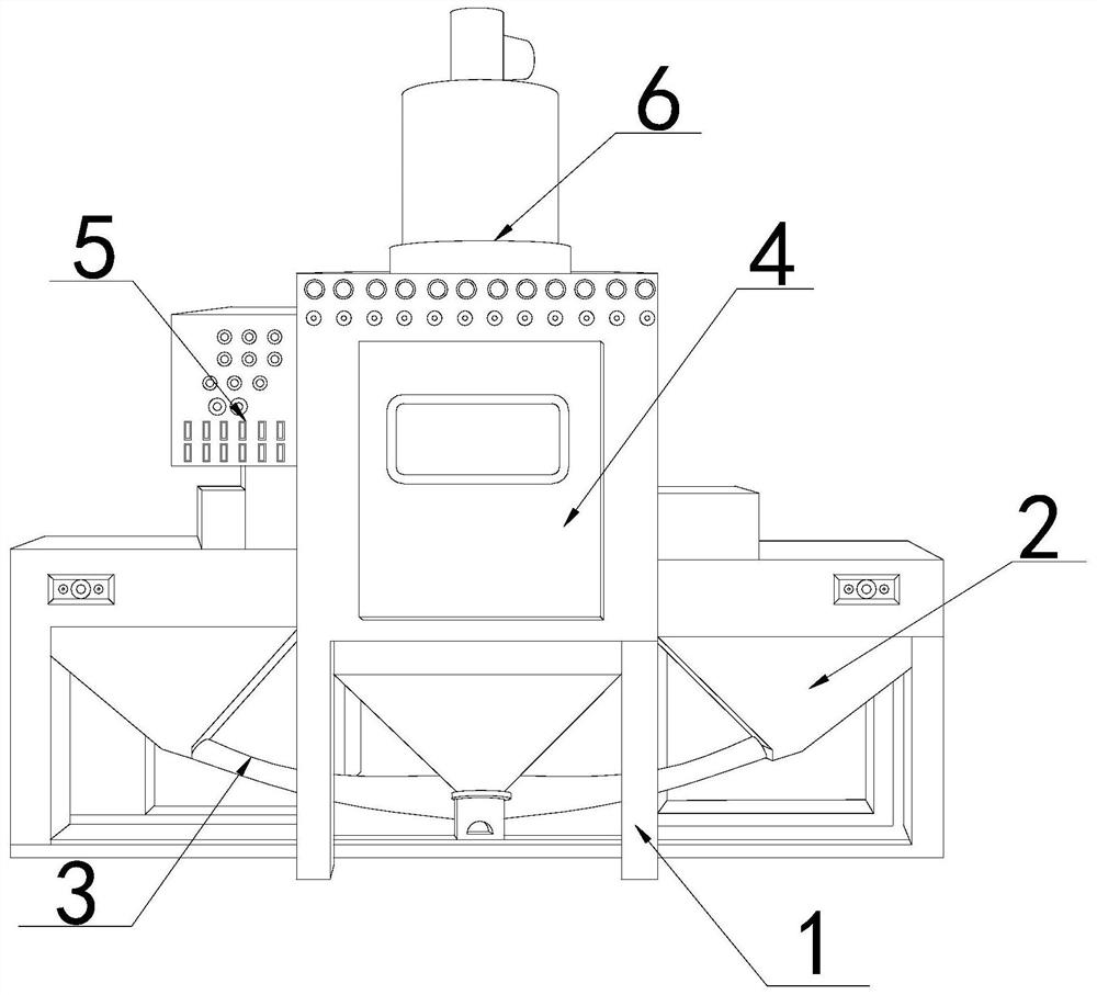
[0028] The present invention provides a conveying type electroplating machine, the structure of which includes a bracket 1, a trough 2, a material delivery pipe 3, a workbench 4, a console 5, and an air pump 6, the trough 2 is installed inside the bracket 1, and the The workbench 4 is fixed on the top of the support 1 , the console 5 is fixed on the left side of the workbench 4 , the air pump 6 is installed on the top of the workbench 4 , and the feed tank 2 is connected with the workbench 4 through the feeding pipe 3 .

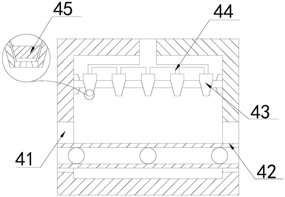
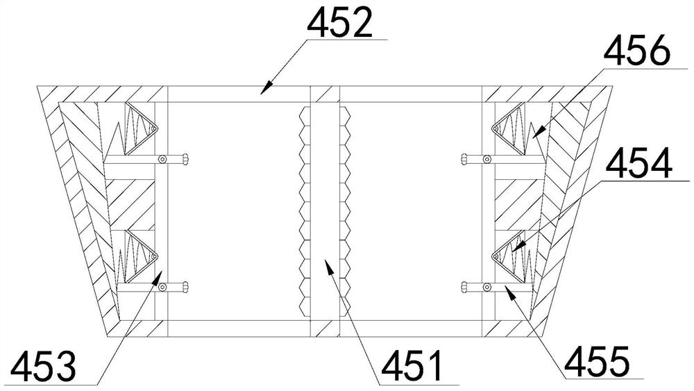
[0029] The workbench 4 is provided with an opening 41, a conveyor belt 42, a nozzle 43, a connecting pipe 44, and a block 45. The openings 41 respectively pass through both sides of the middle and lower part of the workbench 4, and the conveyor belt 42 passes through the opening 41 and is arranged on the workbench. 4, the nozzle 43 is installed inside the workbench 4, the connecting pipe 44 is connect...

Embodiment 2

[0036] as attached Figure 6 to attach Figure 8 Shown:

[0037] Wherein, the side groove a1 is provided with a slide rail a11, a clamping block a12, a slider a13, and a brush block a14. The sliding rail a11 is movably matched, and the brush block a14 is installed on the surface of the clamping block a12. The brush block a14 is an arc-shaped surface, which increases the contact with the contact head a6 and accelerates the removal of abrasive powder on the surface of the contact head a6.

[0038] Wherein, the brush block a14 is provided with a reset block b1, a connecting block b2, and teeth b3, the connecting block b2 is connected with the inner wall of the brush block a14 through the reset block b1, and the teeth b3 are fixed on the surface of the connecting block b2, The teeth b3 are made of metal brushes with relatively high hardness, which can more fully remove the powder with high hardness.

[0039] Wherein, the connection block b2 is provided with an airbag b21, a press...


PUM


Abstract

The invention discloses a conveying type electroplating machine. The conveying type electroplating machine structurally comprises a bracket, a trough, a feed delivery pipe, a working table, a controlconsole and an air pump, wherein the trough is mounted in the bracket, the working table is fixed to the top of the bracket, the control console is fixed to the left side of the working table, the airpump is mounted at the top of the working table, and the trough is connected with the working table through the feed delivery pipe. When a metal plate is subjected to sand blasting, the size of a part of abrasive particles is large, the abrasive particles are pushed by compressed air to be conveyed to spray nozzles, a large-size abrasive material is smashed by clamping blocks, and the condition that normal sand blasting treatment on metal is affected due to the fact that the large-size abrasive particles cannot be sprayed out from the spray nozzles and small holes of the spray nozzles are blocked is reduced; and the smashed abrasive material is powdery and remains on the surface of a contact head, powder on the surface of the contact head is cleared away by teeth arranged in a side groove, and the condition that smashing of the abrasive material is affected due to the fact that the surface of the contact head is filled up and pressure between the contact head and the abrasive materialis reduced because part of the powder is accumulated between bulges and grooves of the contact head is reduced.

Description

technical field [0001] The invention belongs to the field of electroplating, and more specifically relates to a conveying type electroplating machine. Background technique [0002] In order to improve the wear resistance of the metal surface, etc., a layer of metal film is attached to the metal surface by electrolysis to prevent metal oxidation. The ejected abrasive impacts the metal surface, making the metal surface uneven, so that the metal film is fully attached to the metal surface; in the prior art, when the sandblasting machine blasts the metal surface, in order to strengthen the intensity of the spray beam, the diameter of the nozzle is smaller. Small, increase the pressure of the spray material, the size of the abrasive particles formed by the abrasive in the process of processing is different, and some abrasive particles are transported to the nozzle under the push of compressed air, so that the large abrasive particles cannot be ejected from the nozzle. The small ...

Claims


Application Information

Patent Timeline
Patent Type & Authority Applications(China)
IPC IPC(8): B24C1/00B24C3/08B24C5/04B24C9/00C25D5/34
CPCB24C1/00B24C3/08B24C5/04B24C9/003C25D5/34
Inventor 尤德逢
Owner 临漳县万盈贸易有限公司
Learn More