
Step tubular beam welding fixture

A technology for welding tooling and pipe beams, applied in welding equipment, auxiliary welding equipment, welding/cutting auxiliary equipment, etc., can solve the problems that welding accuracy cannot be effectively guaranteed, lack of welding tooling, and high welding accuracy requirements

Pending Publication Date: 2020-10-30
四川丰科汽车部件有限公司
View PDF0 Cites 0 Cited by
  • Summary
  • Abstract
  • Description
  • Claims
  • Application Information

AI Technical Summary

Problems solved by technology

Therefore, in the process of welding the bracket of the step tube beam, the welding precision is required to be high. At present, there is a lack of matching welding equipment, so that the welding precision cannot be effectively guaranteed

Method used


Image

  • Step tubular beam welding fixture
  • Step tubular beam welding fixture
  • Step tubular beam welding fixture

Examples


Embodiment

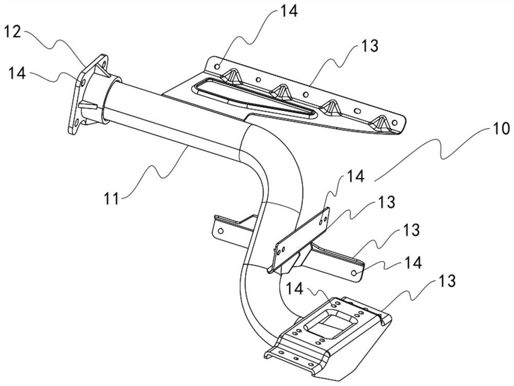
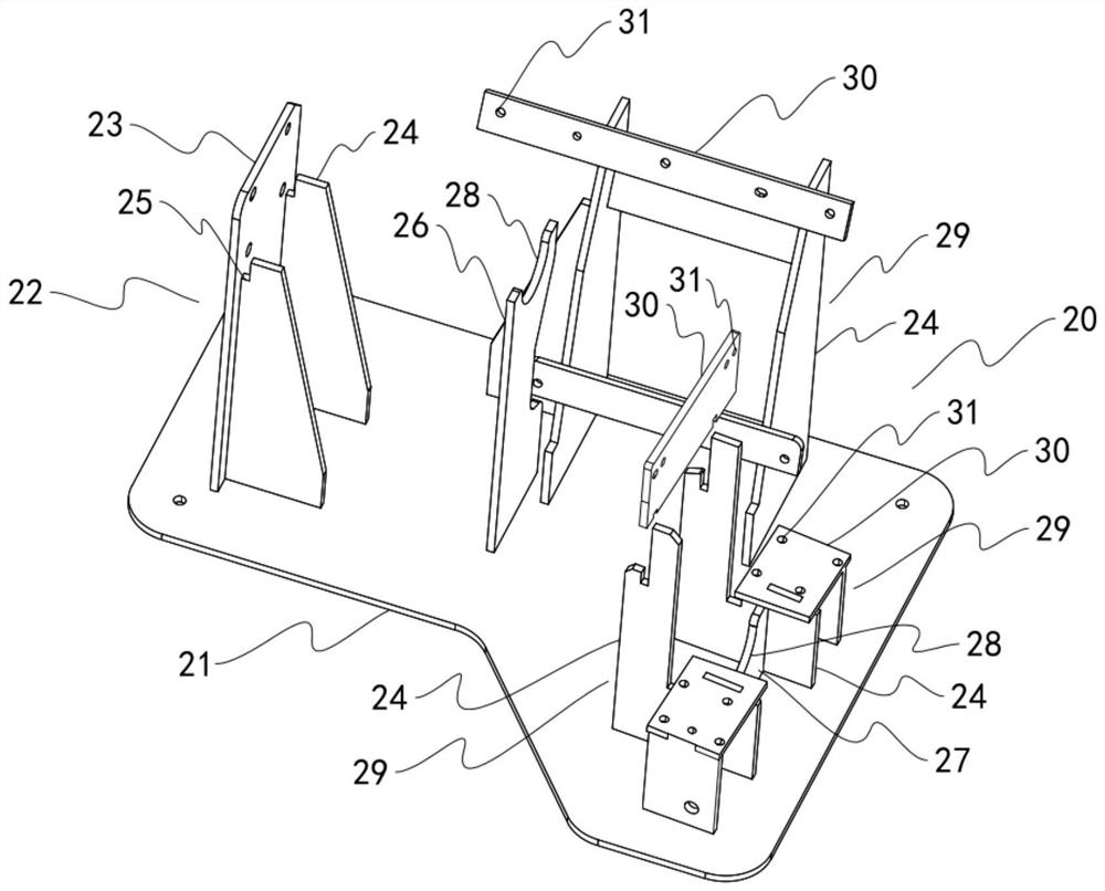
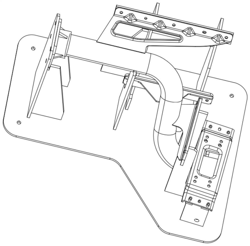
[0017] Such as Figure 1-3 As shown, a step tube beam welding tool, such as figure 1 As shown, the stepping pipe beam 10 includes an "S"-shaped pipe body 11 and a plurality of brackets 13 arranged sequentially along the front end to the rear end of the pipe body 11. The front end of the pipe body 11 is also connected to a flange 12, as figure 2 As shown, the welding tool 20 includes a base 21, and the base 21 is provided with a front end pipe support 22, a middle pipe support 26 and a rear end corresponding to the front end, the front end near the middle, and the rear end of the pipe body 11, respectively. The pipe body support 27, the height of the front end pipe body support 22 and the middle pipe body support 26 is consistent, and the rear end pipe body support 27 is lower than the front end pipe body support 22 and the middle pipe body support 26, The front-end pipe body support 22 is provided with a rectangular slot 25 cooperating with the side of the flange 12, and the...


PUM


Abstract

The invention discloses a step tubular beam welding fixture. The step tubular beam welding fixture comprises an S-shaped tube body and multiple supports, wherein the supports are arranged from the front end to the rear end of the tube body in sequence. A flange is further connected with the front end of the tube body. The welding fixture comprises a base. A front-end tube body supporting piece corresponding to the front end of the tube body is arranged on the base, a middle tube body supporting piece corresponding to the position, close to the middle, of the front end of the tube body is arranged on the base, and a rear-end tube body supporting piece corresponding to the rear end of the tube body is arranged on the base. The front-end tube body supporting piece is as high as the middle tube body supporting piece. The rear-end tube body supporting piece is lower than the front-end tube body supporting piece and the middle tube body supporting piece. A rectangular clamping groove in cooperative positioning with the side edge of the flange is formed in the front-end tube body supporting piece. Arc-shaped clamping grooves in cooperative positioning with the tube body are formed in themiddle tube body supporting piece and the rear-end tube body supporting piece respectively. Multiple support supporting pieces corresponding to the supports are arranged on the base. Connecting plateswhich correspond to the supports and are used to fix the supports are arranged on the support supporting pieces respectively.

Description

technical field [0001] The invention relates to the technical field of mechanical processing equipment, in particular to a stepping tube beam welding tool. Background technique [0002] The stepping tube beam is mainly installed on the girder, on which the brackets with planes are welded according to the needs. The planes of the brackets have holes for installing other components such as fenders, pedals, etc. During the installation process, the position of the holes is adjusted. High standard. Therefore, high welding precision is required in the process of welding the bracket of the stepped pipe beam. At present, there is a lack of matching welding equipment, so that the welding precision cannot be effectively guaranteed. Contents of the invention [0003] In order to solve the problems existing in the prior art, the present invention provides a stepping tube beam welding tool. [0004] The technical scheme adopted in the present invention is: [0005] A stepping pipe ...

Claims


Application Information

Patent Timeline
IPC IPC(8): B23K37/04
CPCB23K37/0443
Inventor 席跃坤
Owner 四川丰科汽车部件有限公司
Learn More