Floating expansion mandrel

A technology of expanding the mandrel and central shaft, which is applied in the field of mechanical processing, to achieve the effect of improving the efficiency of clamping the workpiece, improving the processing efficiency, and eliminating the multi-point floating function

Active Publication Date: 2020-10-30
LANDING GEAR ADVANCED MFG
View PDF10 Cites 2 Cited by
  • Summary
  • Abstract
  • Description
  • Claims
  • Application Information

AI Technical Summary

Problems solved by technology

[0003] In order to overcome the deficiencies of the prior art, the present invention aims to provide a floating expansion mandrel, which can eliminate fixture manufacturing errors, solve the positioning reference problem during part processing, and can also be adapted to special-shaped parts and thinner wall thicknesses parts

Method used


Image

  • Floating expansion mandrel
  • Floating expansion mandrel
  • Floating expansion mandrel

Examples


Embodiment Construction

[0042] The present invention will be described in detail below with reference to the accompanying drawings and examples. It should be noted that, in the case of no conflict, the embodiments of the present invention and the features in the embodiments can be combined with each other. For the convenience of description, if the words "up", "down", "left" and "right" appear in the following, it only means that the directions of up, down, left and right are consistent with the drawings themselves, and do not limit the structure.

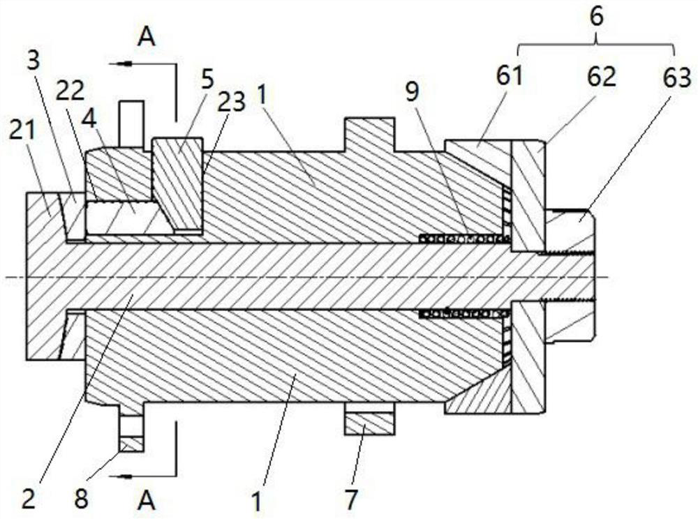
[0043] A floating expansion mandrel such as figure 2 As shown, it includes a positioning base 1 and a stepped central axis 2, the positioning base 1 is a cylinder with a stepped central axis hole along the central axis direction, the stepped central axis 2 is located in the stepped central axis hole, and Cooperate with the small-diameter hole section of the stepped center shaft hole; one end of the stepped center shaft 2 is a spherical tie rod 21, and t...


PUM


Abstract

The invention provides a floating expansion mandrel. Through the arrangement that a radial transmission pin and an axial transmission pin which are perpendicular to each other are matched with each other with tapered surfaces abutting against each other, radial force exerted by a machine bed clamping claw on the radial transmission pin is converted into axial force on the axial transmission pin, so change of direction of transmission force is realized. The axial transmission pin is connected with a spherical gasket in a mode of point contact, and the purpose of free movement can be achieved. The spherical gasket and a spherical push rod can freely rotate via spherical surfaces, and the expansion function of a tensioning member is realized. Multiple positions of the floating expansion mandrel can freely rotate, so the automatic tensioning function can be realized without manual adjustment, and mechanism / fixture manufacturing errors can be eliminated.

Description

technical field [0001] The invention belongs to the field of mechanical processing, and in particular relates to a floating expansion mandrel. Background technique [0002] In terms of mechanical design and processing, in order to improve the strength of parts, the auxiliary structure is usually designed as one with the main structure, which invisibly increases the difficulty of mechanical processing. In mass production, in order to save raw materials, the workpiece to be processed has a small blank margin, and the outer circle cannot be clamped by the machine tool, or the wall thickness of the workpiece to be processed is thin, and clamping the outer circle is likely to cause deformation of the workpiece. If the traditional V-shaped clamping method is used, the processing efficiency will be greatly reduced; if the expansion mandrel clamping method is used, it may cause product quality problems due to inaccurate positioning references. In addition, the manufacturing error of...

Claims


Application Information

Patent Timeline
IPC IPC(8): B23B31/40
CPCB23B31/40
Inventor 陈伟张帆纪欢欢汤伏明石尚
Owner LANDING GEAR ADVANCED MFG
Why Eureka
Try Eureka