
Quantum bit logic gate

A qubit and logic gate technology, applied in the field of qubit logic gates, can solve the problems of complex design of double-qubit logic gates and large interaction of ions

Active Publication Date: 2020-10-27
TSINGHUA UNIV
View PDF2 Cites 3 Cited by
  • Summary
  • Abstract
  • Description
  • Claims
  • Application Information

AI Technical Summary

Problems solved by technology

However, if the ion distance is small, there will be a problem that the ions interact greatly, which makes the design of the two-qubit logic gate more complicated as the number of ions increases.

Method used


Image

  • Quantum bit logic gate
  • Quantum bit logic gate
  • Quantum bit logic gate

Examples


Embodiment Construction

[0035] In order to make the purpose, technical solution and advantages of the present invention more clear, the embodiments of the present invention will be described in detail below in conjunction with the accompanying drawings. It should be noted that, in the case of no conflict, the embodiments in the present application and the features in the embodiments can be combined arbitrarily with each other.

[0036] The steps shown in the flowcharts of the figures may be performed in a computer system, such as a set of computer-executable instructions. Also, although a logical order is shown in the flowcharts, in some cases the steps shown or described may be performed in an order different from that shown or described herein.

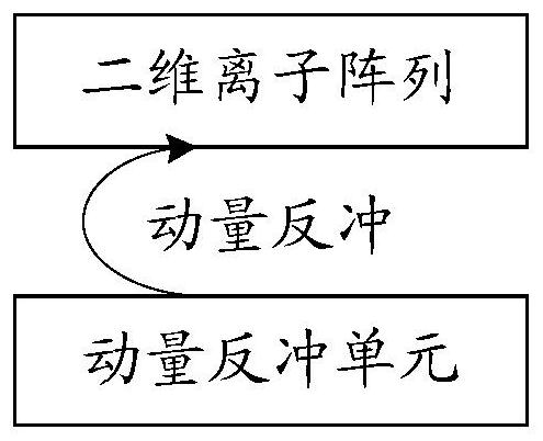
[0037] figure 1 It is a structural block diagram of a qubit logic gate in an embodiment of the present invention, such as figure 1 As shown, including: two-dimensional ion array and momentum recoil unit; where,

[0038] Each ion in the two-dimensional i...


PUM


Abstract

The embodiment of the invention discloses a quantum bit logic gate, which is based on a two-dimensional ion array in which each ion is constrained by a preset simple harmonic potential in a selected direction, and realizes a double-quantum bit logic gate by enabling momentum recoil to act on any two adjacent ions in the two-dimensional ion array. The quantum bit logic gate realized based on the two-dimensional ion array is not limited in ion number; and the operation speed of the double-quantum bit logic gate is ensured through momentum recoil.

Description

technical field [0001] This article involves but is not limited to quantum computer technology, especially a kind of qubit logic gate. Background technique [0002] A quantum computer is a device that uses quantum logic for general-purpose computing. Its basic logic unit is composed of qubits that obey the principles of quantum mechanics. A large number of interacting qubits can physically realize a quantum computer. Compared with traditional computers, on some specific problems, quantum computers can greatly reduce the computational complexity and greatly reduce the time required to complete the calculation. Quantum computers have broad application prospects in basic scientific research, quantum communication and cryptography, artificial intelligence, financial market simulation, and climate change prediction in the future, so they have attracted much attention. [0003] Using arrays of ion qubits trapped in ion traps, various high-fidelity quantum logic gate operations ca...

Claims


Application Information

Patent Timeline
IPC IPC(8): G06N10/00
CPCG06N10/00
Inventor 段路明吴宇恺
Owner TSINGHUA UNIV
Learn More