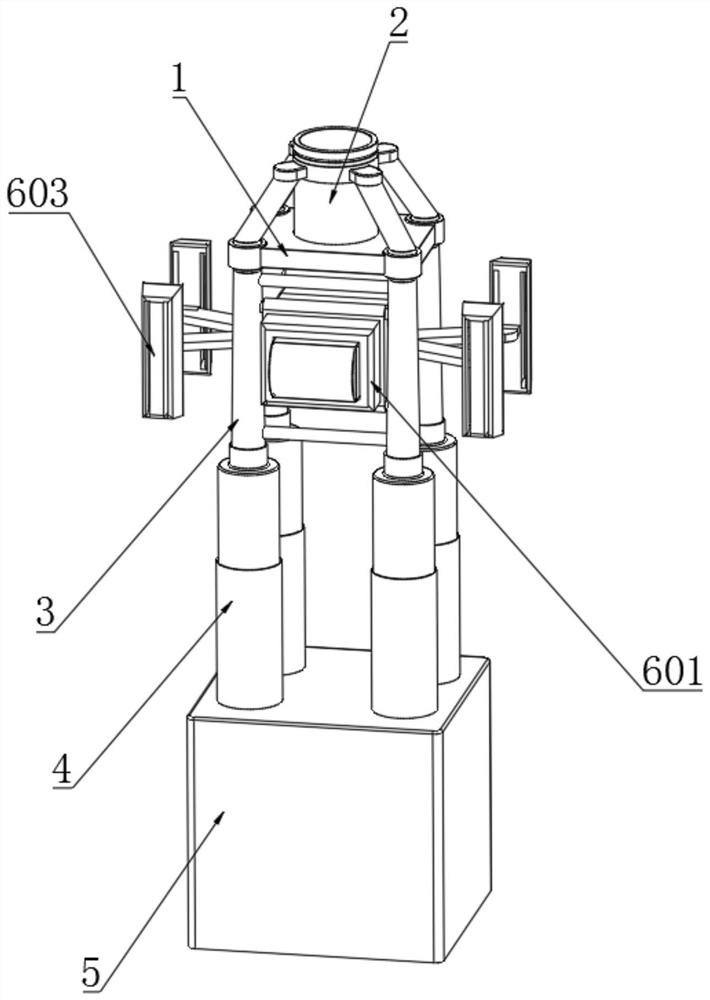
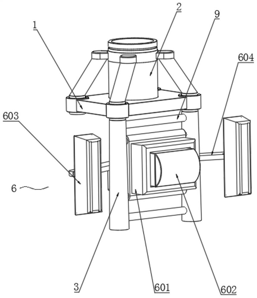
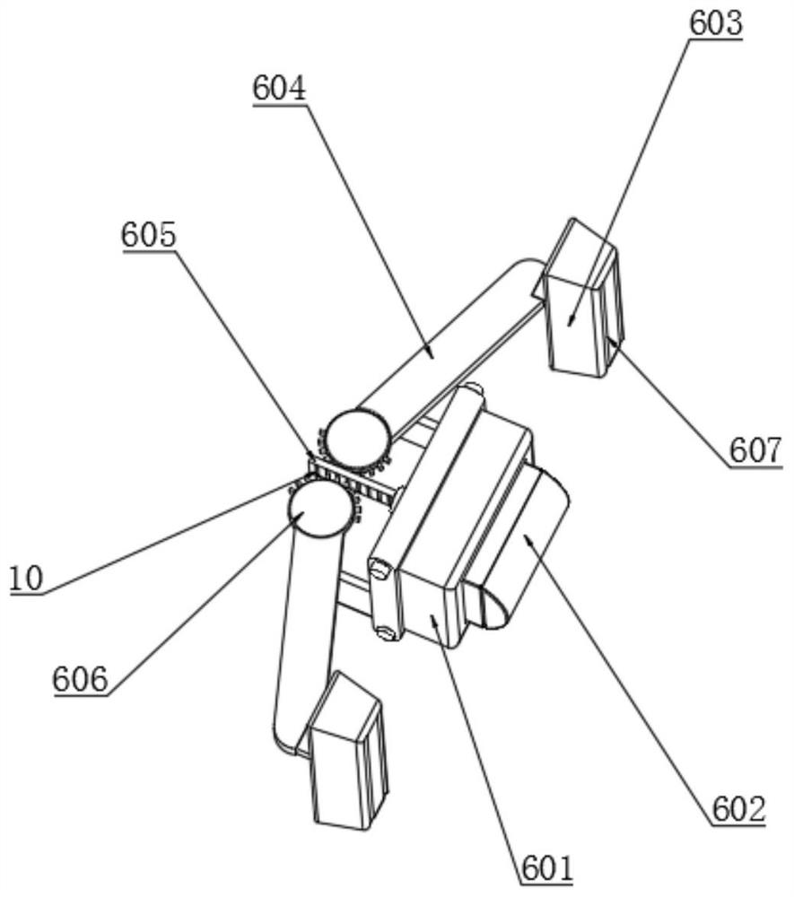
Offshore wind turbine jacket foundation structure

A technology for infrastructure and offshore wind turbines, applied in infrastructure engineering, underwater structures, water conservancy projects, etc., which can solve the problems of easy shaking and inability to realize pressure relief buffer protection of jackets.

Pending Publication Date: 2020-10-27
WUHAN UNIV OF SCI & TECH
View PDF0 Cites 2 Cited by
  • Summary
  • Abstract
  • Description
  • Claims
  • Application Information

AI Technical Summary

Problems solved by technology

[0004] The purpose of the present invention is to provide a foundation structure for offshore wind turbine jackets to solve the problem that the jacket surface of the existing offshore wind turbine jackets proposed in the above background technology is subject to seawater impact for a long time during use, which is prone to shaking and failure. Problems in Realizing the Pressure Relief and Buffer Protection for the Overall Jacket

Method used


Image

  • Offshore wind turbine jacket foundation structure
  • Offshore wind turbine jacket foundation structure
  • Offshore wind turbine jacket foundation structure

Examples


Embodiment 2

[0038] Example 2: See Figure 5 with 6 , the bottom end of the steel pipe pile 4 is installed with a concrete abutment 5, and the compensation component 7 includes a compensation chamber 701, a material injection hollow groove 702, a pressure sensor 703 and a concrete support 704, and the inside of the foundation plate 1 is installed with a concrete support 704, A compensation chamber 701 is installed at the bottom of the concrete support 704 corresponding to the top of the concrete abutment 5, and a hollow groove 702 is provided in the middle of the interior of the concrete support 704, and the inner bottom of the compensation chamber 701 corresponds to the bottom of the compensation chamber 701 Embedded with a pressure sensor 703, when the bottom end of the steel pipe pile 4 collapses at the position of the concrete abutment 5, through the collection of force data difference of multiple pressure sensors 703, through the concrete support 704 in the steel pipe pile 4 The inje...

Embodiment 3

[0039] Example 3: See Figure 7 with 8 , the middle part of the top of the base plate 1 is embedded with a tower fixing seat 2, and the outside of the tower fixing seat 2 is fixedly connected with the base plate 1 through a fixing component 8, which includes a main brace 801, a rubber pad The ring 802 and the drying support ring 803 are fixedly connected between the outside of the tower fixing seat 2 and the base plate 1 through the main diagonal brace 801, and the inside of the tower fixing seat 2 is sleeved with a rubber pad retaining ring 802, and the rubber pad retaining ring 802 One side is socketed with a drying support ring 803, and the exterior of the tower fixing seat 2 can be supported through a plurality of main diagonal braces 801 at the base plate 1, and the tower tube is supported by the rubber pad retaining ring 802 and the drying support ring 803. The inner wall of the fixing seat 2 is tightened so that it fits more closely with the bottom end of the fan.

[...


PUM


Abstract

The invention belongs to the technical field of offshore wind turbine installation, and particularly discloses an offshore wind turbine jacket foundation structure. The offshore wind turbine jacket foundation structure comprises a foundation bedplate, jackets, steel pipe piles, protection assemblies and compensation assemblies, wherein the jackets are clamped to the two sides of the bottom end ofthe outer portion of the foundation bedplate, the protection assemblies are installed inside the jackets, the steel pipe piles are installed at the bottom ends of the exteriors of the jackets, the compensation assemblies are installed inside the steel pipe piles, the protection assemblies are used for buffering and draining offshore waves, the protection assemblies comprise protection covers, arc-shaped buffering top covers and side pressure relief plates, the protection covers are installed between the two jackets, the arc-shaped buffering top covers are embedded inside the protection covers,and the side pressure relief plates are installed on the two sides of the outer portions of the protection covers. According to the offshore wind turbine jacket foundation structure, by arranging theprotection assemblies, the problem that the outer portions of the jackets are impacted by seawater for a long time and is prone to shaking is solved, and pressure relief buffer protection on the whole jackets is achieved.

Description

technical field [0001] The invention relates to the technical field of installation of offshore wind turbines, in particular to a basic structure of an offshore wind turbine jacket. Background technique [0002] Fan is the customary abbreviation for gas compression and gas conveying machinery in my country. Usually, fans include ventilators, blowers, wind generators, gas compression and gas conveying machinery convert rotating mechanical energy into gas pressure energy and kinetic energy, and The main structural components of the fan are the impeller, the casing, the air inlet, the bracket, the motor, the pulley, the coupling and the muffler, and the offshore fan can use the wind on the sea. [0003] When installing offshore wind turbines, it is necessary to use the foundation structure of the jacket of the offshore wind turbine to fix it. However, the jacket foundation structure of the existing offshore wind turbines is subject to seawater impact for a long time when the exi...

Claims


Application Information

Patent Timeline
Patent Type & Authority Applications(China)
IPC IPC(8): E02B17/00E02D27/42E02D31/10
CPCE02B17/00E02B2017/0091E02D27/425E02D31/10
Inventor 褚丹灵林庭玉张敏鸿
Owner WUHAN UNIV OF SCI & TECH
Why Eureka
Try Eureka