
Movable steel rail shearing machine and application method

A shearing machine, mobile technology, applied in the direction of shearing device, shearing machine equipment, accessories of shearing machine, etc., can solve the problems of unguaranteed safety and environmental pollution.

Pending Publication Date: 2020-10-27
HUBEI LIDI MACHINE TOOL
View PDF0 Cites 0 Cited by
  • Summary
  • Abstract
  • Description
  • Claims
  • Application Information

AI Technical Summary

Problems solved by technology

[0002] With the continuous development of society and economy, especially the development of railways at home and abroad, the rapid rise of high-speed railways, most of the ordinary railway lines built before need to be replaced, and in the northern local area, a large number of railways left over from the War of Resistance Against Japan need to be demolished. A large number of rails are produced, and the current rails are cut by oxygen cutting, which not only cannot guarantee safety, but also causes pollution to the environment

Method used


Image

  • Movable steel rail shearing machine and application method
  • Movable steel rail shearing machine and application method
  • Movable steel rail shearing machine and application method

Examples


Embodiment 1

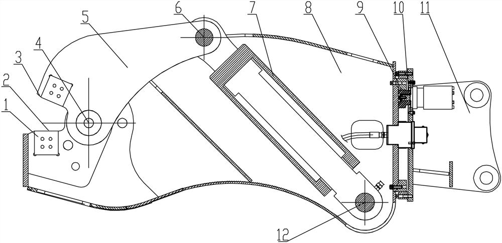
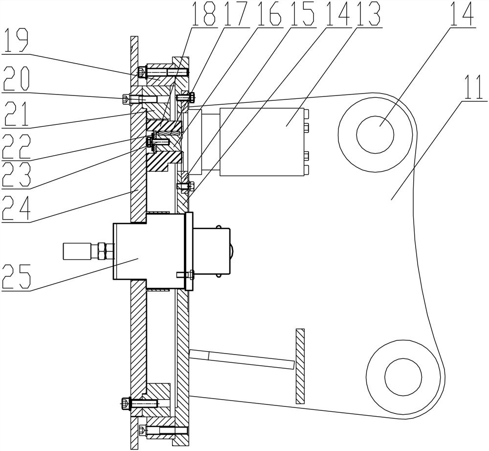
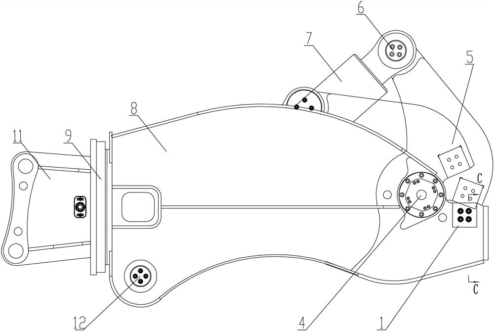
[0038] see Figure 1-6 , a mobile rail shearing machine, which includes a knife body connecting seat 11, a rotating disc 24 is installed on the outer wall of the knife body connecting seat 11 through a rotary drive mechanism 9, and a fixed knife is fixedly installed on the outer end surface of the rotating disc 24 body 8, the head of the fixed cutter body 8 is hinged with a movable cutter body 5 through the kingpin shaft system 4, and a shearing power device is arranged between the movable cutter body 5 and the fixed cutter body 8; the fixed cutter body 8 and the head of the moving knife body 5 are respectively processed with a first cutout 2 and a second cutout 3, and the first cutout 2 and the second cutout 3 are respectively equipped with a shear blade 1 . By adopting the above structure, the rail shearing machine can be used for shearing rails. In the specific use process, the above-mentioned movable knife body 5 is driven by a shearing power device, and then through the...

Embodiment 2

[0054] The method of using the mobile rail shearing machine for rail shearing comprises the following steps:

[0055] Step 1: Fix the shearing machine to the end of the mechanical arm of the mobile device through the knife body connecting seat 11;

[0056] Step 2: Use mobile equipment to move to the location of the rail;

[0057] Step 3: Operate the mechanical arm to open the fixed knife body 8 and the movable knife body 5 of the shearing machine, and make the position of the knife edge clamp the rail;

[0058] Step 4: Start the shearing power device, drive the movable cutter body 5 through the shearing oil cylinder 7 of the shearing power device, and cut the rail through the cooperation between the movable cutter body 5 and the fixed cutter body 8 .


PUM


Abstract

The invention provides a movable steel rail shearing machine and an application method. The movable steel rail shearing machine comprises a cutter body connecting seat. A rotating disc is mounted on the outer side wall of the cutter body connecting seat through a rotary drive mechanism. A fixed cutter body is fixedly mounted on the outer end face of the rotating disc. A moving cutter body is hinged to the head of the fixed cutter body through a main pin shaft system. A shear power device is arranged between the moving cutter body and the fixed cutter body. A first shear opening and a second shear opening are machined at the heads of the fixed cutter body and the moving cutter body correspondingly, and shear blades are mounted on the first shear opening and the second shear opening. The shearing machine can be used for steel rail shearing, then the traditional flame cutting manner is replaced, the steel rail shearing efficiency is improved, and the labor intensity of workers is reduced.

Description

technical field [0001] The invention relates to the field of rail shearing machines, in particular to a movable rail shearing machine. The main pin shaft adopts an assembly mode of interference fit and clearance fit. Background technique [0002] With the continuous development of society and economy, especially the development of railways at home and abroad, the rapid rise of high-speed railways, most of the ordinary railway lines built before need to be replaced, and in the northern local area, a large number of railways left over from the War of Resistance Against Japan need to be demolished. A large number of rails are produced, and the current rails are cut by oxygen cutting, which not only cannot guarantee safety, but also causes pollution to the environment. Contents of the invention [0003] The object of the present invention is to provide a mobile rail shearing machine and its use method. This shearing machine can be used for shearing rails, and then replaces the...

Claims


Application Information

Patent Timeline
Patent Type & Authority Applications(China)
IPC IPC(8): B23D31/00B23D33/02B23Q11/12
CPCB23D31/00B23D33/02B23Q11/12
Inventor 林高黄黎曙
Owner HUBEI LIDI MACHINE TOOL
Learn More