Eureka AIR delivers breakthrough ideas for toughest innovation challenges, trusted by R&D personnel around the world.

Fault processing method and device and power grid commutation high-voltage direct-current power transmission system

A technology of direct current transmission system and fault handling method, which is applied in the direction of power transmission AC network, emergency protection circuit device, electrical components, etc., and can solve problems such as endangering the safe operation of power electronic equipment, affecting power transmission, system impact, etc.

Active Publication Date: 2020-10-23
TSINGHUA UNIV
View PDF6 Cites 3 Cited by
  • Summary
  • Abstract
  • Description
  • Claims
  • Application Information

AI Technical Summary

Problems solved by technology

The existing DC transmission system mostly uses overhead transmission lines, the transmission distance is long, but the operating environment is complex and the failure rate is high. When a fault occurs, the DC transmission system will form a short circuit for a short time, affecting power transmission, and generating a huge DC fault current. This will further endanger the safe operation of power electronic equipment. Due to the large DC transmission capacity, if the fault is not handled properly, it will cause serious accidents such as cascading faults and blackouts. Therefore, the rapid removal and restoration of DC line faults will improve the reliability of power supply and maintain system stability. sex matters
The LCC-HVDC (grid commutated high-voltage direct current transmission) system has a fault restart function (DC-Line Fault Recovery Sequences, DFRS) to quickly clear the fault and try to restart. However, before restarting, it does not judge whether the fault disappears. For permanent faults, multiple restarts will still be performed, which will cause multiple impacts on the system, prolong the operation time of the safety device, and cause more serious losses.

Method used


Image

  • Fault processing method and device and power grid commutation high-voltage direct-current power transmission system
  • Fault processing method and device and power grid commutation high-voltage direct-current power transmission system
  • Fault processing method and device and power grid commutation high-voltage direct-current power transmission system

Examples


Embodiment 1

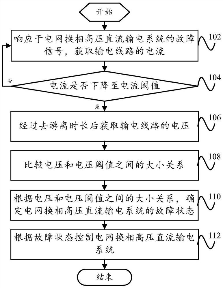
[0048] like figure 1 As shown, according to the embodiment of the first aspect of the present invention, a fault handling method for a grid-commutated HVDC transmission system is proposed, the method comprising:

[0049] Step 102, obtaining the current of the transmission line in response to the fault signal of the grid commutation HVDC transmission system;

[0050] Step 104, whether the current drops to the current threshold, if so, go to step 106, if not, go to step 102;

[0051] Step 106, obtain the voltage of the transmission line after the de-ionization time;

[0052] Step 108, comparing the magnitude relationship between the voltage and the voltage threshold;

[0053] Step 110, according to the size relationship between the voltage and the voltage threshold, determine the fault state of the grid commutated HVDC transmission system;

[0054] Step 112, controlling the grid commutation HVDC transmission system according to the fault state.

[0055] In this embodiment, a...

Embodiment 2

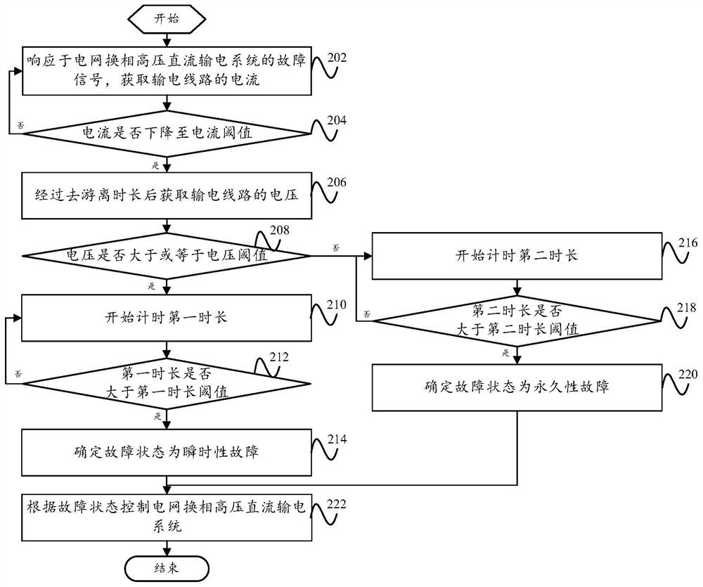
[0058] like figure 2 As shown, according to an embodiment of the present invention, a fault handling method for grid commutation HVDC transmission system is proposed, the method includes:

[0059] Step 202, obtaining the current of the transmission line in response to the fault signal of the grid commutation HVDC transmission system;

[0060] Step 204, whether the current drops to the current threshold, if so, go to step 206, if not, go to step 202;

[0061] Step 206, obtain the voltage of the transmission line after the de-ionization period;

[0062] Step 208, whether the voltage is greater than or equal to the voltage threshold, if so, go to step 210, if not, go to step 216;

[0063] Step 210, start timing the first duration;

[0064] Step 212, whether the first duration is greater than the first duration threshold, if so, proceed to step 214, if not, proceed to step 210;

[0065] Step 214, determining that the fault state is a transient fault;

[0066] Step 216, start...

Embodiment 3

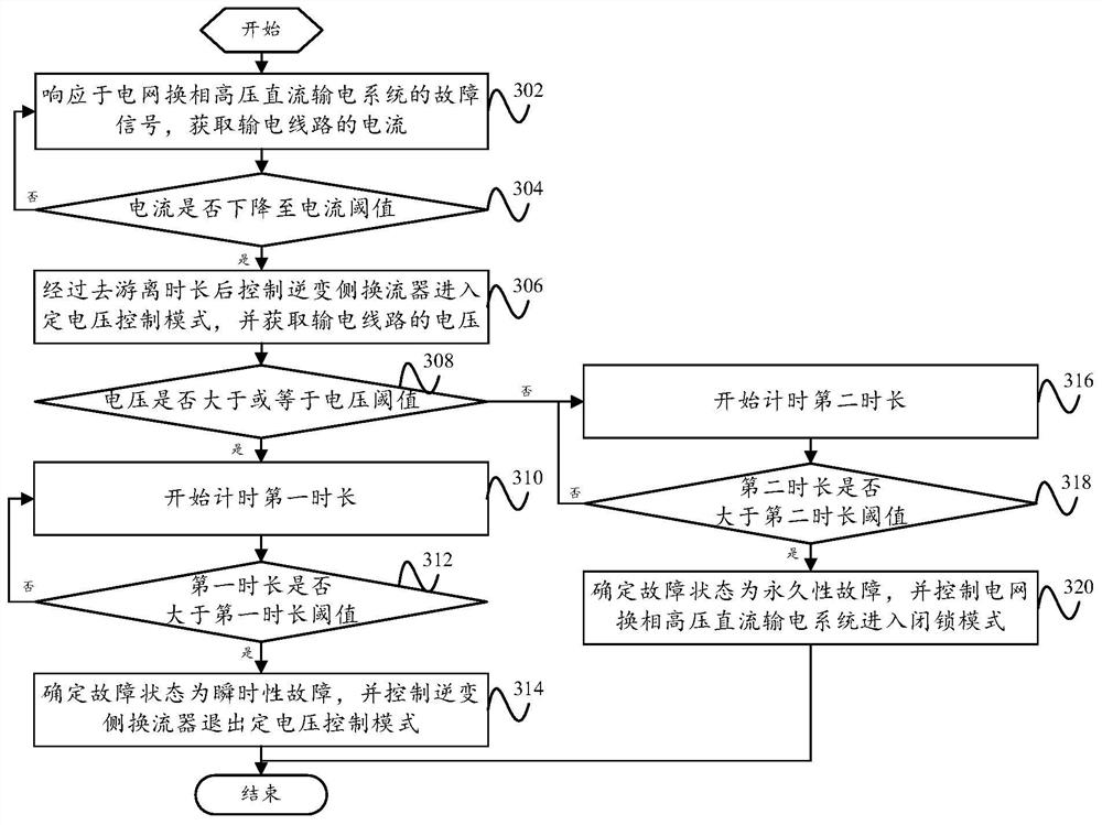
[0073] like image 3 As shown, according to an embodiment of the present invention, a fault handling method for grid commutation HVDC transmission system is proposed, the method includes:

[0074] Step 302, obtaining the current of the transmission line in response to the fault signal of the grid commutation HVDC transmission system;

[0075] Step 304, whether the current drops to the current threshold, if so, go to step 306, if not, go to step 302;

[0076] Step 306, control the inverter-side converter to enter the constant voltage control mode after the de-ionization time elapses, and obtain the voltage of the transmission line;

[0077] Step 308, whether the voltage is greater than or equal to the voltage threshold, if so, go to step 310, if not, go to step 316;

[0078] Step 310, start counting the first duration;

[0079] Step 312, whether the first duration is greater than the first duration threshold, if so, proceed to step 314, if not, proceed to step 310;

[0080]...


PUM


Abstract

The invention provides a fault processing method and device and a power grid commutation high-voltage direct-current power transmission system. The method comprises the steps: in response to a fault signal of a direct-current power transmission system, acquiring the current of a power transmission line; obtaining the voltage of the power transmission line after the deionization duration when the current drops to the current threshold value; comparing the magnitude relationship between the voltage and the voltage threshold; determining a fault state of the direct-current power transmission system according to a magnitude relation between the voltage and a voltage threshold value; and controlling the DC transmission system according to the fault state. Therefore, the fault state can be identified after the deionization stage is finished; and the locking sequence is executed and the fault line is isolated only after the instantaneous fault disappears and under the permanent fault, so thatthe fault self-adaptive restart of the direct-current power transmission system is realized, the secondary impact on the power transmission system caused by restart of the permanent fault is effectively avoided, the equipment safety is ensured, the safety of the direct-current power transmission system is improved, and the service life is prolonged.

Description

technical field [0001] The present invention relates to the technical field of direct current transmission systems, in particular to a fault handling method for grid commutation high voltage direct current transmission systems, a fault handling device for grid commutation high voltage direct current transmission systems and a grid commutation high voltage direct current transmission system system. Background technique [0002] Compared with AC transmission technology, DC transmission technology has the advantages of small loss, long transmission distance, large transmission capacity, and easy control, and has been developed rapidly. The existing DC transmission system mostly uses overhead transmission lines, the transmission distance is long, but the operating environment is complex and the failure rate is high. When a fault occurs, the DC transmission system will form a short circuit for a short time, affecting power transmission, and generating a huge DC fault current. Th...

Claims


Application Information

Patent Timeline
Patent Type & Authority Applications(China)
IPC IPC(8): H02H7/26H02J3/36
CPCH02H7/268H02J3/36Y02E60/60
Inventor 董新洲蔡静
Owner TSINGHUA UNIV
Why Eureka
Eureka Blog
Learn More