
Fluorescent penetrant flaw detection visual identification system

A visual recognition and fluorescent penetration technology, applied in the field of testing equipment, can solve problems such as inconsistent testing quality, large differences in testing results, and reduced production efficiency.

Inactive Publication Date: 2020-10-23
东方蓝天钛金科技有限公司
View PDF14 Cites 2 Cited by
  • Summary
  • Abstract
  • Description
  • Claims
  • Application Information

AI Technical Summary

Problems solved by technology

[0004] Due to the complex characteristics of the penetration flaw detection process, manual visual observation is widely used to evaluate the fluorescence display formed by the surface defects of the workpiece. In the flaw detection of a large number of workpieces, this manual observation method will greatly reduce production efficiency. Differences in vision and observation methods of personnel will also lead to large differences in test results, resulting in great inconsistency in test quality

Method used


Image

  • Fluorescent penetrant flaw detection visual identification system
  • Fluorescent penetrant flaw detection visual identification system
  • Fluorescent penetrant flaw detection visual identification system

Examples


Embodiment Construction

[0038] The principles and features of the present invention are described below in conjunction with the accompanying drawings, and the examples given are only used to explain the present invention, and are not intended to limit the scope of the present invention.

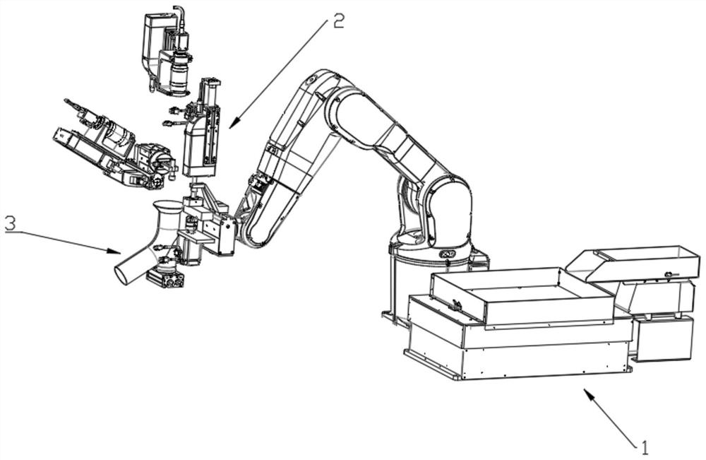
[0039] Please refer to figure 1 As shown in , it is a schematic structural diagram of the visual recognition system for fluorescent penetrant detection of the present invention. In order to highlight the core components and their interrelationships, the basic brackets carrying each component are hidden in the figure. A visual recognition system for fluorescent penetrant flaw detection, comprising: a feeding part 1, a detection part 2, a feeding part 3 and a control part;

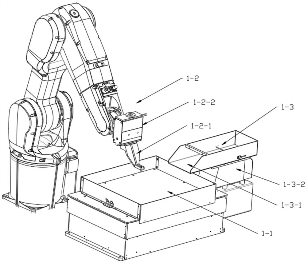
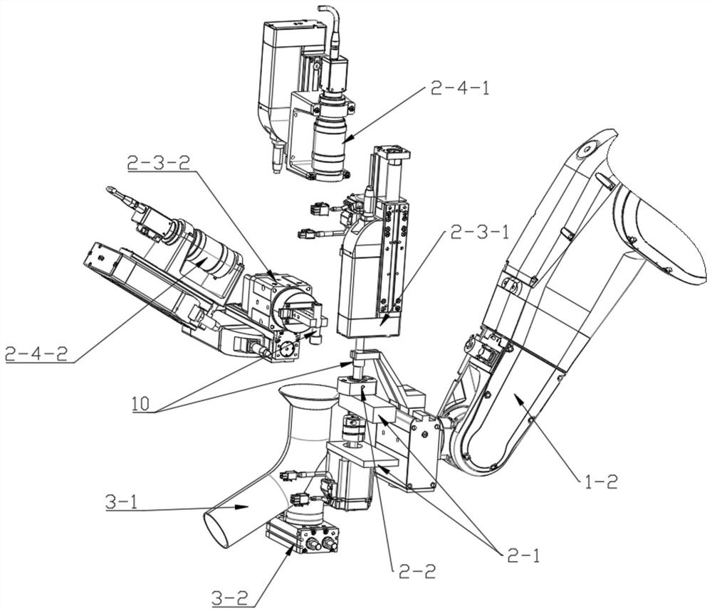
[0040] The feeding part 1 is used to provide the workpiece 10 to be tested for the detection part 2, including a vibrating feeding tray 1-1, a manipulator 1-2 and a feeding bin 1-3; the feeding bin 1-3 is located in the Above the side of the vibr...


PUM

PropertyMeasurementUnit
wavelengthaaaaaaaaaa

Abstract

The invention discloses a fluorescent penetrant flaw detection visual identification system which comprises a feeding part, a detection part, a discharging part and a control part. The feeding part isused for providing a to-be-detected workpiece for the detection part; the detection part comprises a base, a rotating platform, a workpiece clamping device, an ultraviolet irradiation lamp and a detection camera, and the rotating platform, the workpiece clamping device, the ultraviolet irradiation lamp and the detection camera are fixed on the base; the workpiece clamping device comprises a workpiece end surface clamping device and a workpiece circumferential surface clamping device; the detection camera comprises a workpiece end surface camera and a workpiece circumferential surface camera;the workpiece end surface camera is vertically arranged above the rotating platform and is used for detecting the end surface of the to-be-detected workpiece; the workpiece circumferential surface camera is horizontally arranged on a side surface of the rotating platform and is used for detecting the circumferential surface of the to-be-detected workpiece; and the rotating platform is used for bearing the to-be-detected workpiece transferred from the feeding part and driving the to-be-detected workpiece to rotate. Therefore, the fluorescent penetrant flaw detection visual identification systemprovided by the invention can realize 360-degree dead-angle-free automatic inspection of the workpiece, and avoids an inspection blind area and subjectivity of an inspection result.

Description

technical field [0001] The invention relates to the field of detection equipment, in particular to a visual recognition system for fluorescent penetrant flaw detection. Background technique [0002] Mechanical parts will have discontinuity defects such as cracks, corrosion, and pores during work. Such defects seriously threaten the safety and reliability of existing mechanical equipment. There are countless accidents of parts failure and fracture due to surface defects. As a mature non-destructive testing method, flaw detection can effectively detect and reveal discontinuity defects on the surface of engineering materials. [0003] The principle of fluorescent penetrant flaw detection is: apply a layer of fluorescent penetrant on the surface of the workpiece to be inspected, use capillary action to make the fluorescent penetrant penetrate into the opening defects on the surface of the workpiece, remove the excess penetrant on the surface with a cleaning agent, and then apply...

Claims


Application Information

Patent Timeline
Patent Type & Authority Applications(China)
IPC IPC(8): G01N21/91G01N21/01
CPCG01N21/91G01N21/01
Inventor 钱煜刘高峰姜斌李霞王文智
Owner 东方蓝天钛金科技有限公司
Learn More