


Quick Research
Generate reliable direction feasibility study reports for your R&D in just a few steps.

Technical Q&A
Discover and master advanced knowledge NOW. Basics, ideas, possibilities, all at once.

Find Solutions
As an expert in R&D theories, this can generate solutions to your technical problems instantly.

Evaluate Feasibility
Analyze your overall solution with one click, know your potential R&D risks in advance.

Monitor Landscape
Get weekly tech updates, stay abreast of the latest tech innovations and key insights.
Illumination intensity detection device for agricultural big data
A technology of light intensity detection and big data, which is applied in measuring devices, photometry, optical radiation measurement, etc., and can solve problems such as single detection methods and detection errors
- Summary
- Abstract
- Description
- Claims
- Application Information
AI Technical Summary
Problems solved by technology
Method used
Image


Examples
Embodiment 1
[0019] Such as figure 1 As shown, a light intensity detection device for agricultural big data includes a daylighting box 1 and a light intensity detector 2, the top surface of the daylighting box 1 is a transparent glass plate, and a horizontally arranged transparent box 3 is installed in the daylighting box 1, transparent The box body 3 is filled with mixed gas of nitrogen dioxide and dinitrogen tetroxide, the mixed gas is an equilibrium mixture, and the equilibrium moves with the change of temperature, and the reaction equation is N 2 o 4 ==2NO 2 (reversible), the side wall of the transparent box body 3 is communicated with an air bag through an air guide tube, and when the mixed gas of nitrogen dioxide and dinitrogen tetroxide is heated and expanded, part of the mixed gas enters the air bag under the action of air pressure to play a buffering role and avoid The air pressure in the transparent box 3 is too large, the bottom of the transparent box 3 is equipped with a phot...
Embodiment 2
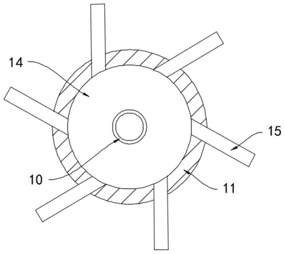
[0026] Such as figure 2 As shown, the difference between this embodiment and Embodiment 1 is that: a cavity 14 is provided in the mounting seat 11, and a plurality of exhaust pipes 15 are fixedly connected to the side wall of the mounting seat 11, and the plurality of exhaust pipes 15 are in the form of The annular arrays are arranged and communicated with the cavity 14 , and the included angle between the exhaust pipe 15 and the tangential direction of the mounting seat 11 is 60°.
[0027] In this embodiment, during the downward movement of the permanent magnet ring 8, part of the gas in the adjustment cylinder 5 is discharged from the exhaust pipe 15, and the gas generates a reverse thrust on the exhaust pipe 15, because the exhaust pipe 15 and the mounting seat 11 The included angle in the tangential direction is 60°, the thrust acts on the mounting base 11, and a torsional component force is generated to it, then the mounting base 11 drives the light intensity detector 2 ...
PUM
 Abstract
Description
Claims
Application Information
 - R&D Engineer
- R&D Manager
- IP Professional
- Industry Leading Data Capabilities
- Powerful AI technology
- Patent DNA Extraction
Browse by: Latest US Patents, China's latest patents, Technical Efficacy Thesaurus, Application Domain, Technology Topic, Popular Technical Reports.
© 2024 PatSnap. All rights reserved.Legal|Privacy policy|Modern Slavery Act Transparency Statement|Sitemap|About US| Contact US: help@patsnap.com