
Cascade heat accumulating and supplying system and method

A heating system, cascade heat exchange technology, applied in heating systems, heating methods, household heating and other directions, can solve the output power fluctuations, can not completely solve the temperature fluctuations, poor thermal conductivity and other problems

Active Publication Date: 2020-10-23
BEIJING HTN PIPELINE EQUIP
View PDF19 Cites 2 Cited by
  • Summary
  • Abstract
  • Description
  • Claims
  • Application Information

AI Technical Summary

Problems solved by technology

High-temperature sensible heat storage is widely used due to its simple operation and high energy storage density. However, as the temperature of the heat storage body drops, the output power will fluctuate greatly and the heat transfer will be unstable.
Chinese patents ZL201610318705.7 and ZL 201610323747.X proposed mainly adopting the method of parallel and series pipelines, and by switching the corresponding pipelines in different temperature ranges to increase the heat exchange area, the heat exchange power of the high-temperature heat storage body is achieved. Fluctuations within a certain allowable range, but this scheme cannot completely solve the problem of temperature fluctuations, and can only obtain stable heat supply within a certain fluctuation range
Phase change heat storage has the advantages of large phase change latent heat, narrow phase change temperature range, and can significantly reduce the size of the heat storage device. It is a hot research topic at home and abroad. However, phase change heat storage has poor thermal conductivity, Problems such as low energy storage density and serious corrosion
Chinese patent CN203518746U discloses a multi-stage heat recovery phase change accumulator, which is composed of multiple single-stage phase change accumulators filled with different phase change temperature materials connected in series, which improves the heat absorption rate and heat dissipation rate of phase change materials. Heat rate, but the patent uses a spiral coil heat exchange structure, which is generally limited by the material and is difficult to apply to high temperature environments
This method simplifies the structure of the multi-stage recovery heat accumulator and improves the heat absorption and release rate of the phase change material, but it cannot solve the problem of low energy storage density of the phase change heat accumulator
[0005] The high-temperature heat accumulator with high energy storage density is unstable in heat transfer power, and the control and pipeline layout are relatively complicated. The medium-low temperature phase change heat accumulator has low energy storage density and does not have the ability to stabilize and controllable output.

Method used


Image

  • Cascade heat accumulating and supplying system and method
  • Cascade heat accumulating and supplying system and method
  • Cascade heat accumulating and supplying system and method

Examples


Embodiment Construction

[0034] The present invention will be further described in detail below in conjunction with the accompanying drawings, so that those skilled in the art can implement it with reference to the description.

[0035] It should be understood that terms such as "having", "comprising" and "including" used herein do not exclude the presence or addition of one or more other elements or combinations thereof.

[0036]It should be noted that the experimental methods described in the following embodiments, unless otherwise specified, are conventional methods, and the reagents and materials, if not otherwise specified, can be obtained from commercial sources; in the description of the present invention, It should be noted that, unless otherwise clearly stipulated and limited, the terms "installation", "connection" and "arrangement" should be interpreted in a broad sense, for example, it can be fixedly connected, arranged, or detachably connected, arranged, or Connect and set in one piece. T...


PUM


Abstract

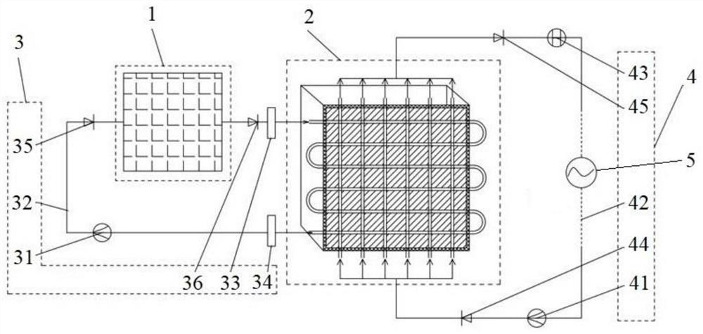
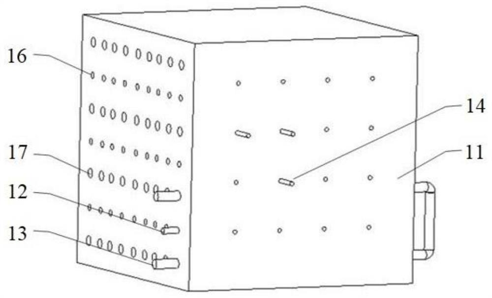
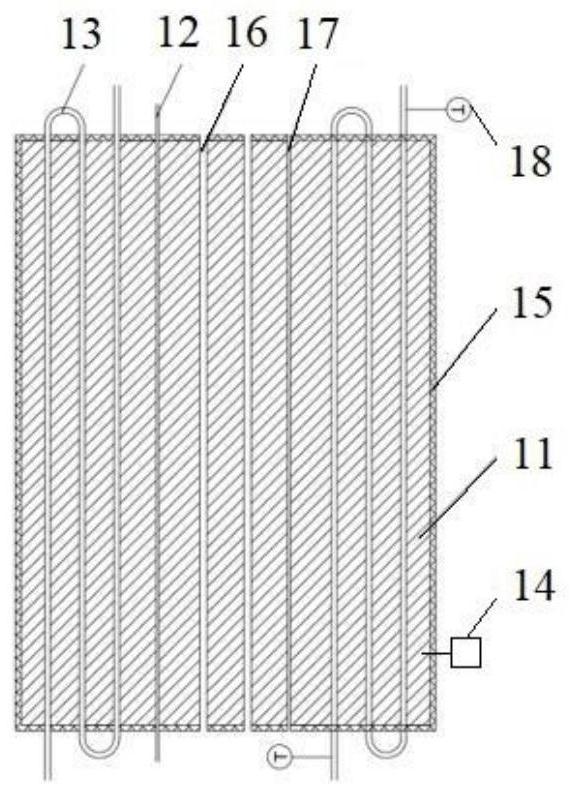
The invention discloses a cascade heat accumulating and supplying system. The cascade heat accumulating and supplying system comprises a cascade heat-exchanging loop and a heat-supplying loop, whereinthe cascade heat-exchanging loop is composed of a cascade heat-exchanging circulating pump, a high-temperature heat-accumulating module and a transitional constant-current heat accumulating and exchanging module which are sequentially connected through a cascade heat-exchanging circulating pipeline, and the heat-supplying loop is composed of the transitional constant-current heat accumulating andexchanging module and a heat-supplying circulating pump which are sequentially connected through a heat-supplying pipeline; the high-temperature heat-accumulating module comprises a high-temperatureheat accumulator which is internally provided with a heat-exchanging pipeline; both the inlet end and the outlet end of the heat-exchanging pipeline are connected with the cascade heat-exchanging circulating pipeline; the transitional constant-current heat accumulating and exchanging module comprises a medium-and-low-temperature phase-change heat accumulator which is internally provided with a plurality of heating heat-exchanging pipes and heat-releasing heat-exchanging pipes, and both the inlet ends and the outlet ends of the heating heat-exchanging pipes are connected with the cascade heat-exchanging circulating pipeline; both the inlet ends and the outlet ends of the heat-releasing heat-exchanging pipes are connected with the heat-supplying pipeline; and circulating heat transfer substances are arranged in the cascade heat-exchanging circulating pipeline and the heat-supplying pipeline correspondingly, and heat using equipment is arranged between the transitional constant-current heat accumulating and exchanging module and the heat-supplying circulating pump. The cascade heat accumulating and supplying system is large in heat accumulation amount and stable in power supplying.

Description

technical field [0001] The invention relates to the technical field of heat storage and heat supply. More specifically, the present invention relates to a cascade thermal storage heating system and method. Background technique [0002] In order to rationally use energy, improve energy utilization efficiency, and adjust the time difference between the energy supply side and the energy demand side, energy storage technology has received strong support and development in recent years. Heat storage technology is mainly divided into three types: thermochemical heat storage, sensible heat heat storage and phase change heat storage. [0003] Sensible heat storage is a method of storing heat through the specific heat capacity and temperature difference of the heat storage body, and storing or releasing heat through the increase or decrease of temperature. High-temperature sensible heat storage is widely used because of its simple operation and high energy storage density. However,...

Claims


Application Information

Patent Timeline
IPC IPC(8): F24D11/00F24D15/02F24D19/10
CPCF24D11/002F24D15/02F24D19/1006
Inventor 王岩张立申卜一王薇宋杨
Owner BEIJING HTN PIPELINE EQUIP
Learn More