
Residual current operated circuit breaker

A residual current and circuit breaker technology, which is applied to circuit breaker components, circuits, switches operated by ground fault current, etc., can solve the problems of increased production processes, weight increase, lack of positioning structure of springs, etc., and achieve improved positioning and coordination effects , Reduce the wiring process, improve the effect of the contact area

Pending Publication Date: 2020-10-16
DELIXI ELECTRIC
View PDF0 Cites 1 Cited by
  • Summary
  • Abstract
  • Description
  • Claims
  • Application Information

AI Technical Summary

Problems solved by technology

[0004] (1) The production or purchase cost of the circuit board is relatively high, and the volume is relatively large, which occupies more space inside the housing, which is not conducive to the miniaturization and compactness of the overall structure of the product, and the sensitivity and reliability are also poor;
[0005] (2) The tripping coil and the circuit board are independent of each other. During assembly, the two need to be installed separately, and the tripping coil and the circuit board need to be electrically connected through wires, which not only occupies a lot of space inside the housing space, and it is easy to shake, which is not conducive to the cover assembly between the base and the cover;
[0006] (3) The spring in the tripping coil lacks an effective positioning structure, and it is easy to come out during the closing process of the cover plate, which is inconvenient to assemble;
[0007] (4) The other end of the shaft needs to be fixed by a fixing plate, and the setting of the fixing plate will bring about the problems of increasing the overall volume of the product, increasing the weight, increasing the cost, and increasing the production process;
[0008] (5) The moving contact piece and the static contact piece of the test device are easy to contact with the circuit board during use, resulting in a short circuit and affecting the test function

Method used


Image

  • Residual current operated circuit breaker
  • Residual current operated circuit breaker
  • Residual current operated circuit breaker

Examples


Embodiment Construction

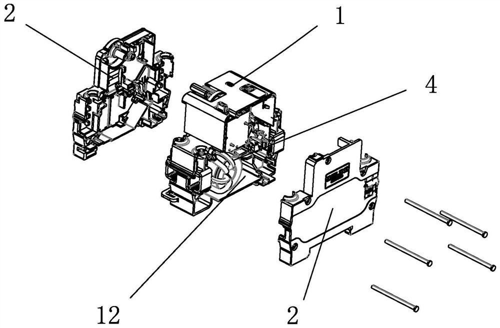
[0067] Embodiments of the residual current operated circuit breaker of the present invention are as follows Figure 1-19 As shown: it includes a base 1, a first concave cavity 11 is opened on one side of the base 1, a second concave cavity 12 is opened on the other side of the base 1, and the first concave cavity 11 and the second concave cavity 12 pass through The cover plates 2 arranged on both sides of the base 1 are closed, and the base 1 and the cover plates 2 are inserted into each other and connected through screws or rivets.

[0068] The residual current operated circuit breaker also includes a circuit breaker module 3 and a leakage protection module 4 respectively arranged in the first cavity 11 and the second cavity 12 and shielded and protected by the cover plate 2. The leakage protection module 4 includes The zero-sequence transformer 41 and the tripping mechanism, the tripping mechanism includes a tripping coil 42, the zero-sequence transformer 41 includes a magne...


PUM


Abstract

The invention discloses a residual current operated circuit breaker, which comprises a base and a cover plate. A concave cavity is formed in one side of the base; the electric leakage protection module comprises a zero sequence mutual inductor and a tripping mechanism. The tripping mechanism comprises a tripping coil, the zero sequence mutual inductor comprises a magnetic ring and a secondary winding. A first wire and a second wire are further included and matched with the magnetic ring in a penetrating mode. The tripping coil comprises a coil framework and a coil winding; a circuit board is connected between the secondary winding and the tripping coil; the first wire and the second wire are both wound on the zero sequence mutual inductor and penetrate through an inner hole of the zero sequence mutual inductor at least twice, a plurality of discrete components used for achieving filtering of output signals of the mutual inductor and switching devices are arranged on the circuit board,and the secondary winding and the tripping coil are electrically connected through the discrete components. The device is convenient to install, the existing product structure can be simplified, and the product weight and the production cost are reduced.

Description

technical field [0001] The invention relates to a residual current operated circuit breaker. Background technique [0002] The residual current operated circuit breaker is a circuit breaker with leakage protection function. Its shell is generally composed of a base and a cover plate. There are concave cavities on both sides of the base. The cover plate can seal the cavity. It accommodates the leakage protection module and the circuit breaker module. The leakage protection module includes internal components such as zero-sequence transformer, tripping mechanism, circuit board, moving and static contacts, and arc extinguishing chamber. Some of the internal components include tension springs, moving contacts Heads, connecting rods, swing rods, etc. need to be positioned or rotated through shafts. One end of these shafts is inserted and fixed on the base, and the other end is inserted and fixed on the fixed plate connected to the base. The cover plate The inner side is usually ...

Claims


Application Information

Patent Timeline
IPC IPC(8): H01H71/02H01H71/08H01H71/24H01H73/04H01H83/04H01H83/14
CPCH01H71/0264H01H71/08H01H71/24H01H73/04H01H83/04H01H83/14
Inventor 徐方剑祁卫华许利战
Owner DELIXI ELECTRIC
Learn More