Concrete pouring method for prefabricated stand column

A technology in concrete and concrete, applied in the direction of manufacturing tools, supply devices, ceramic molding machines, etc., can solve the problems of aggravating the possibility of concrete segregation, poor quality of concrete pouring, deformation of stirrups and tie bars, etc., and achieve high practical value , The structure is simple, the effect of reducing the drop height and speed

Inactive Publication Date: 2020-10-16
SHANGHAI NO 4 CONSTR
View PDF5 Cites 0 Cited by
  • Summary
  • Abstract
  • Description
  • Claims
  • Application Information

AI Technical Summary

Problems solved by technology

[0002] When the prefabricated components of the pier column are manufactured in the factory, the conventional automobile pump is used for concrete pouring. Due to the high height of the column and the dense arrangement of steel bars, it is difficult for the pouring hose of the pump truck to extend into the steel cage skeleton during the concrete pouring of the column. Pumping concrete directly at the top of the column leads to a high concrete blanking height, and high concrete drop height is prone to concrete segregation, and the concrete will continuously impact the column hoops and tie bars during the concrete drop process, which further aggravates the The possibility of concrete segregation also causes some deformation and damage to the stirrups and tie bars, which is not good for the quality of concrete pouring

Method used


Image

  • Concrete pouring method for prefabricated stand column
  • Concrete pouring method for prefabricated stand column
  • Concrete pouring method for prefabricated stand column

Examples


Embodiment Construction

[0028] The present invention will be described in detail below in conjunction with specific embodiments. The following examples will help those skilled in the art to further understand the present invention, but do not limit the present invention in any form. It should be noted that those skilled in the art can make several modifications and improvements without departing from the concept of the present invention. These all belong to the protection scope of the present invention.

[0029] This embodiment provides a method for pouring prefabricated column concrete, including:

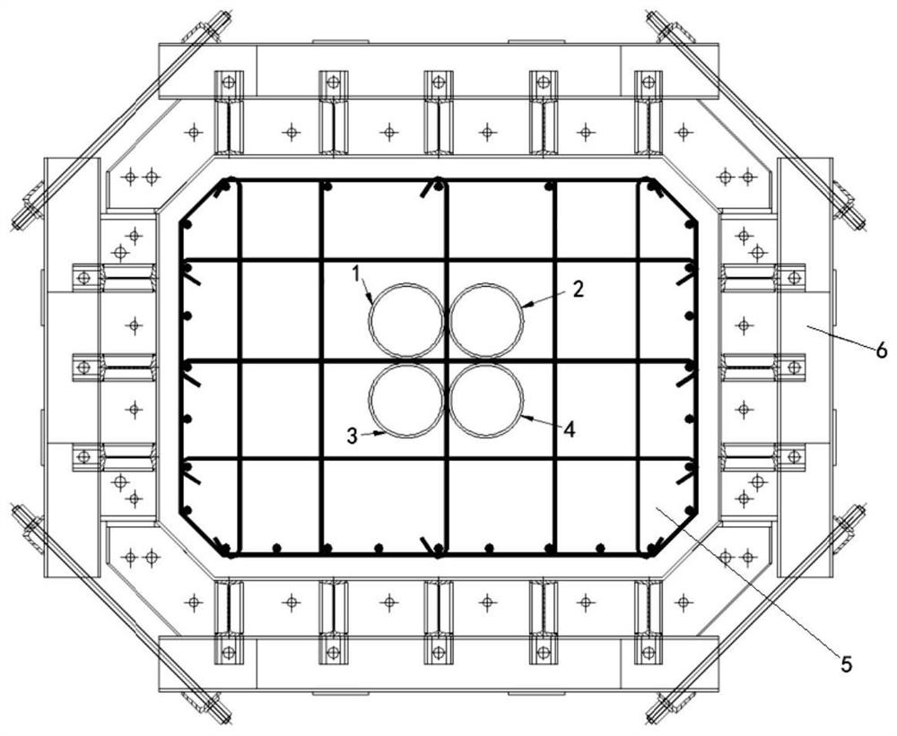
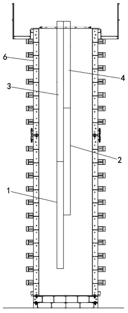
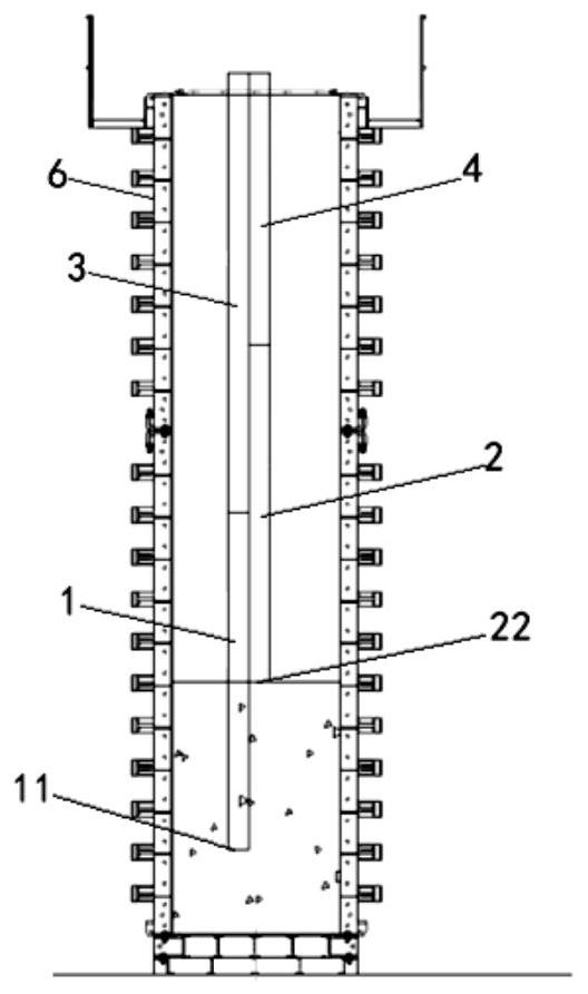
[0030] Clamp the column reinforcement cage 5 with the prefabricated column formwork 6 and fix them on the pouring pedestal, arrange a group of pouring conduits of different lengths in the column reinforcement cage 5 along the length direction, and close the lower opening of the longest pouring conduit in the group to The bottom surface of the column reinforcement cage 5, the distances from the lower op...


PUM

PropertyMeasurementUnit
diameteraaaaaaaaaa
lengthaaaaaaaaaa
lengthaaaaaaaaaa

Abstract

The invention provides a concrete pouring method for a prefabricated stand column. The concrete pouring method includes the steps of disposing a group of pouring guide pipes of different lengths in astand column reinforcement cage in the length direction, fixing upper ports of the pouring pipes to the top of the stand column reinforcement cage, making a lower port of the longest pouring guide pipe in the group close to the bottom face of the stand column reinforcing cage and lower ports of the other pouring guide pipes have an increasing distance from the bottom face of the stand column reinforcing cage in sequence, pouring concrete into a mold through the longest pouring guide pipe first after the pouring guide pipes are fixed so that the lower port of the longest pouring guide pipe canbe embedded in the concrete when the concrete pouring amount increases, continuing pouring concrete through the second longest pouring guide pipe when the concrete pouring height is close to the lowerport of the second longest pouring guide pipe and detaching the longest pouring guide pipe, and repeatedly executing the aforementioned steps according to the lengths of the pouring guide pipes fromlong to short until poured concrete is close to the top of the stand column reinforcing cage. By means of the method, drop height and speed of concrete are effectively reduced, and concrete disintegration is avoided.

Description

technical field [0001] The invention relates to the construction field of prefabricated columns in the construction technology of prefabricated bridges, in particular to a method for pouring concrete of prefabricated columns. Background technique [0002] When the prefabricated components of the pier column are manufactured in the factory, the conventional automobile pump is used for concrete pouring. Due to the high height of the column and the dense arrangement of steel bars, it is difficult for the pouring hose of the pump truck to extend into the steel cage skeleton during the concrete pouring of the column. Pumping concrete directly at the top of the column leads to a high concrete blanking height, and high concrete drop height is prone to concrete segregation, and the concrete will continuously impact the column hoops and tie bars during the concrete drop process, which further aggravates the The possibility of concrete segregation also causes some deformation and dama...

Claims


Application Information

Patent Timeline
Patent Type & Authority Applications(China)
IPC IPC(8): B28B13/02B28B23/02B28B23/00
CPCB28B13/02B28B23/00B28B23/02
Inventor 郑晏华李申杰干华铭徐晨泽孙俊张剑宇董少白张锡霖王灏周君李晨辉姚艳曹佳雯
Owner SHANGHAI NO 4 CONSTR
Why Eureka
Try Eureka