Multiple part synchronous assembling method and clamp and automatic assembling device thereof
An assembly fixture and assembly method technology, applied in the direction of workpiece clamping devices, assembly machines, manufacturing tools, etc., can solve the problems of unstable assembly quality, low production efficiency, high production cost, etc., and achieve overcoming complicated assembly, convenient operation, and assembly fast effect
- Summary
- Abstract
- Description
- Claims
- Application Information
AI Technical Summary
Problems solved by technology
Method used
Image


Examples
Embodiment 1
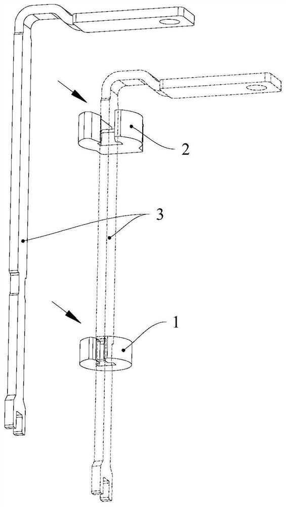
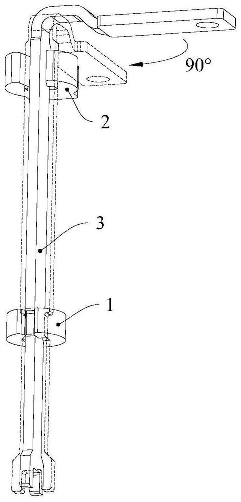
[0067] As shown in Fig. 2, this embodiment provides a multi-part synchronous assembly method for positioning and assembling at least one first component and at least one second component, including the following steps:
[0068] S1. placing the first component and the second component in a jig provided with a void, and placing the second component on the first component, and partially exposing the first component to the void;
[0069] S2. Applying pressure to the part of the first component exposed to the void so as to be twisted and fixed relative to the second component.
[0070] This embodiment creatively proposes the use of clamps to complete the torsional assembly and fixation between two or more parts, which overcomes the technical problems of complicated assembly of small-volume parts, low assembly efficiency, unstable assembly quality, and high assembly cost. First, pre-install and position the parts to be assembled through the fixture, and then apply pressure to one of...
Embodiment 2
[0075] Such as image 3 As shown, this embodiment provides a multi-part synchronous assembly fixture applying the method described in Embodiment 1, for positioning and assembling at least one first component and at least one second component, including a positioning plate 300 and a pressing plate 200 , the positioning plate 300 is provided with a part positioning groove 320 and a first avoidance hole 310, the part positioning groove 320 is used for positioning the first part and the second part which are pre-packaged with each other, and the first avoidance hole 310 Used to partially expose the first part; the pressing plate 200 covers the positioning plate 300, and the pressing plate 200 is provided with a second avoidance hole 210 corresponding to the first avoidance hole 310, and the second avoidance hole 210 is used for The part of the first component is exposed; the external force passes through the first escape hole 310 or the second escape hole 210 to exert pressure on ...
Embodiment 3
[0079] As a preferred implementation of embodiment 2, the difference between this embodiment and embodiment 2 is that, as Figure 5 As shown, the multi-part synchronous assembly fixture also includes a flip plate 100, the flip plate 100 is used to receive external force, and the flip plate 100 is provided with a flip corresponding to the first avoidance hole 310 or the second avoidance hole 210. The stake 110 is used to apply pressure to the part of the first component exposed to the first avoidance hole 310 or the second avoidance hole 210 so that it is twisted and fixed relative to the second component. Optionally, the overturning stake 110 is positioned and fixed on the overturning plate 100 through the positioning groove of the overturning stake 110 provided on the overturning plate 100 .
[0080] For the jig that completes the torsional assembly and fixing of multiple groups of parts at one time, the addition of the flip plate 100 with the flip pile 110 can undoubtedly br...
PUM
 Abstract
Description
Claims
Application Information
 - Generate Ideas
- Intellectual Property
- Life Sciences
- Materials
- Tech Scout
- Unparalleled Data Quality
- Higher Quality Content
- 60% Fewer Hallucinations
Browse by: Latest US Patents, China's latest patents, Technical Efficacy Thesaurus, Application Domain, Technology Topic, Popular Technical Reports.
© 2025 PatSnap. All rights reserved.Legal|Privacy policy|Modern Slavery Act Transparency Statement|Sitemap|About US| Contact US: help@patsnap.com