
Sulfur condenser pipe head structure and welding method thereof

A condenser and tube head technology, which is applied in the field of sulfur condenser tube head structure and its welding, can solve the problems of difficult penetration and low pass rate of radiographic inspection, etc.

Pending Publication Date: 2020-10-16
SHANGHAI LANBIN PETROCHEM EQUIP +2
View PDF0 Cites 1 Cited by
  • Summary
  • Abstract
  • Description
  • Claims
  • Application Information

AI Technical Summary

Problems solved by technology

[0004] The second object of the present invention is to provide a welding method for the head structure of the sulfur condenser, which solves the problems that the welding root of the conventional head is not easy to penetrate and the qualified rate of radiographic inspection is low

Method used


Image

  • Sulfur condenser pipe head structure and welding method thereof
  • Sulfur condenser pipe head structure and welding method thereof
  • Sulfur condenser pipe head structure and welding method thereof

Examples


Embodiment 1

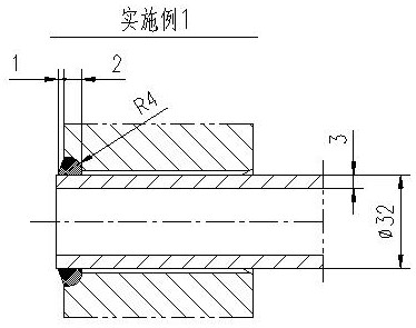
[0023] Example 1, such as image 3 As shown, a sulfur condenser tube head structure, the heat exchange tube specification is Φ32x3mm, the groove depth of the tube plate hole is 2mm, that is, the thickness of the groove weld is 2mm; The radius of the calculated arc is 2mm, and the minimum welding space at the root is considered as 4mm. The actual radius of the arc is 4mm; considering the wall thickness of the heat exchange tube is 3mm, the thickness of the uniform corrosion combined weld is not less than 3mm, and the overhang of the tube head is 1.5mm , fillet weld 1mm.

Embodiment 2

[0024] Example 2, such as Figure 4 As shown, a sulfur condenser tube head structure, the heat exchange tube specification is Φ45x5mm, the groove depth of the tube plate hole is 4mm, that is, the thickness of the groove weld is 4mm; the shape of the groove is arc-shaped, calculated by 1.5 times the depth The radius of the arc is 6mm, and the minimum welding space at the root is considered to be 4mm. The actual radius of the arc is 6mm; the wall thickness of the heat exchange tube is 5mm, and the combined weld thickness of the uniform corrosion is not less than 5mm, and the overhang of the tube head is 0.5mm , No fillet welds.

[0025] The welding method of the sulfur condenser pipe head structure described in above-mentioned embodiment 1 and embodiment 2, concrete steps are as follows:

[0026] (1) Control the groove depth deviation of tube sheet 2 to be (0, +0.3mm); it can effectively ensure the penetration of the root, and there will be no root infusion.

[0027] (2) Contr...


PUM


Abstract

The invention discloses a sulfur condenser pipe head structure. A pipe plate pipe hole groove adopts a whole arc structure, a heat exchange pipe extends out of the pipe plate end face outwards, a pipeplate and the heat exchange pipe are connected into a whole body through a combined welding seam, the thickness of the welding seam is not smaller than the thickness of the heat exchange pipe, a welding method of the sulfur condenser pipe head structure comprises the steps that manual argon tungsten arc welding is adopted, autogenous welding is adopted in a first pass, and other welding passes adopt filler wire welding; and during bottoming welding, the current is 220 to 240 A, the voltage is 11 to 15 V, the welding speed is larger than or equal to 100 mm / min, the linear energy is 1.452 to 2.16 KJ / mm, during filler wire welding, a 1.6 mm welding wire is adopted, the welding current is 180 to 200 A, the voltage is 11 to 15 V, the welding speed is larger than or equal to 110 mm / min, and thelinear energy is 1.08 to 1.636KJ / mm. the pipe head root type and welding application space are optimized, a key control measure of heat exchange pipe and pipe plate welding can be given out, the problem that a conventional pipe head welding root is not prone to complete penetration, is prone to tungsten inclusion, and is low in ray detection yield can be solved, meanwhile, the combined welding seam type ensures the enough welding seam thickness, and the severe needs of the corrosion environment of a sulfur plant can be met.

Description

technical field [0001] The invention provides a pipe head structure of a sulfur condenser and a welding method thereof, and relates to the technical field of sulfur condensers of sulfur recovery devices in industries such as petroleum, chemical industry, and coal chemical industry. Background technique [0002] The sulfur condenser is mainly used to cool the process gas of the sulfur recovery unit. The process gas contains hydrogen sulfide, sulfur dioxide, carbon dioxide and other components, which is a typical stress corrosion and acid dew point corrosion environment. The connection joint between heat exchange tube and tube sheet (tube head structure) has been used in the above environment for a long time. If the weld thickness of the tube head is insufficient or there are welding defects, there is a greater risk of leakage; similar applications have introduced the tube head radiographic inspection technology, Strictly control the quality of the pipe head to reduce the risk...

Claims


Application Information

Patent Timeline
IPC IPC(8): B23K9/167B23K9/235B23K33/00F28F9/18
CPCB23K9/167B23K9/235B23K33/00F28F9/18
Inventor 陈晶尹依娜马一鸣张峥金彦枫张洪涛徐成张淑雁刘泉王颖博汪沈阳罗沿予南楠赵国栋潘瑞霞
Owner SHANGHAI LANBIN PETROCHEM EQUIP
Learn More