
Welding with trailing extrusion device for friction stir welding and welding with trailing extrusion method thereof

A technology of friction stir welding and extrusion device, which is applied in welding equipment, non-electric welding equipment, metal processing equipment, etc., can solve the problems of cumbersome clamping process, large clamping size, and narrow welding space, etc., to broaden the scope of application , Increase the welding space and the effect of high-quality connection

Inactive Publication Date: 2014-06-11
SHENYANG INST OF AUTOMATION - CHINESE ACAD OF SCI
View PDF7 Cites 9 Cited by
  • Summary
  • Abstract
  • Description
  • Claims
  • Application Information

AI Technical Summary

Problems solved by technology

[0003] The object of the present invention is to provide a welding extrusion device for friction stir welding and its welding extrusion method, which solves the problem that the size of the fixture is too large and the welder is welded when the friction stir welding method is used to weld a metal plate with a large width. The problem of cumbersome front-loading process; and the problem of narrow welding space for welding tools when welding metal sheets with a small width

Method used


Image

  • Welding with trailing extrusion device for friction stir welding and welding with trailing extrusion method thereof
  • Welding with trailing extrusion device for friction stir welding and welding with trailing extrusion method thereof
  • Welding with trailing extrusion device for friction stir welding and welding with trailing extrusion method thereof

Examples


Embodiment Construction

[0022] The present invention will be described in further detail below in conjunction with the accompanying drawings.

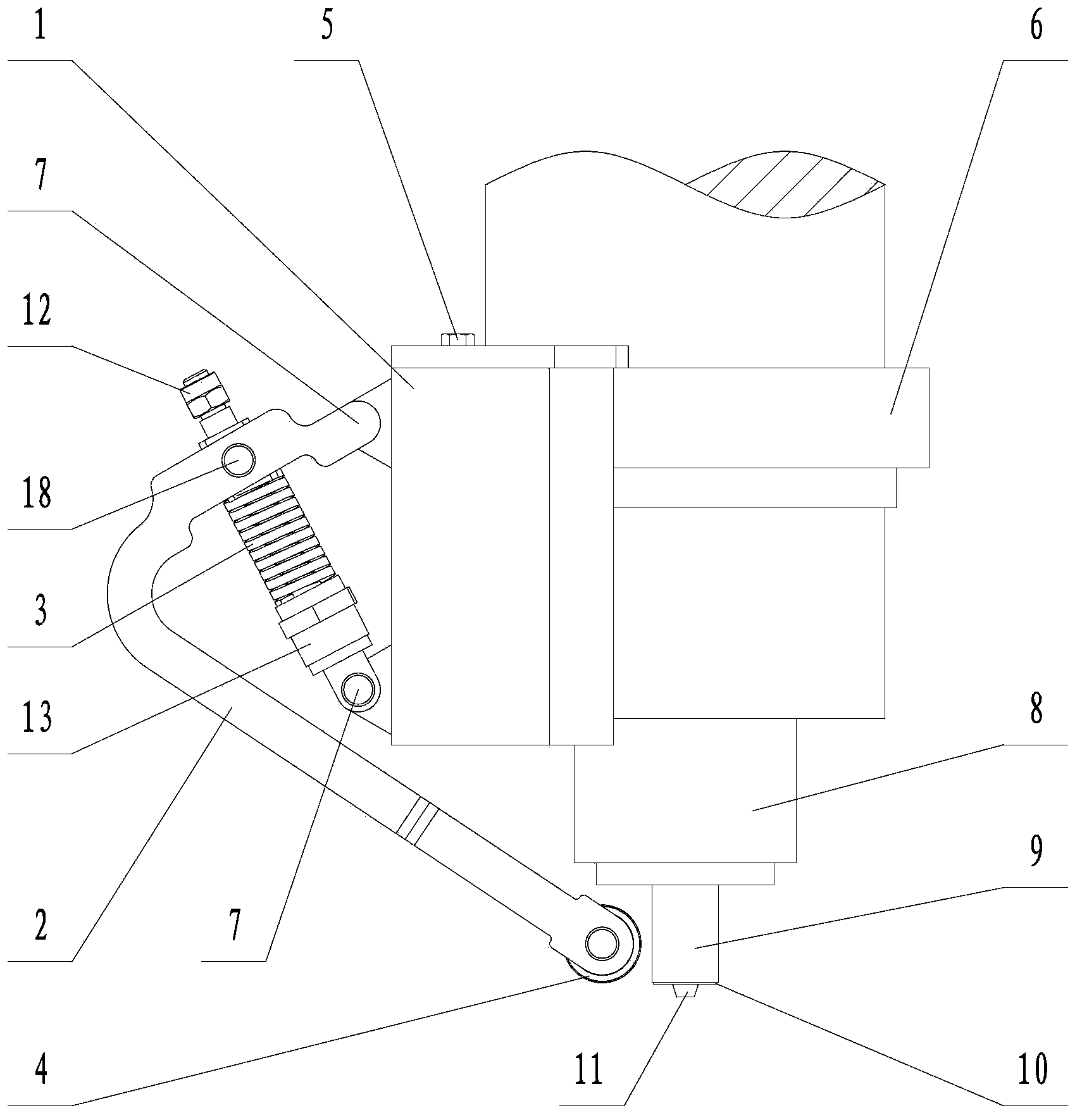
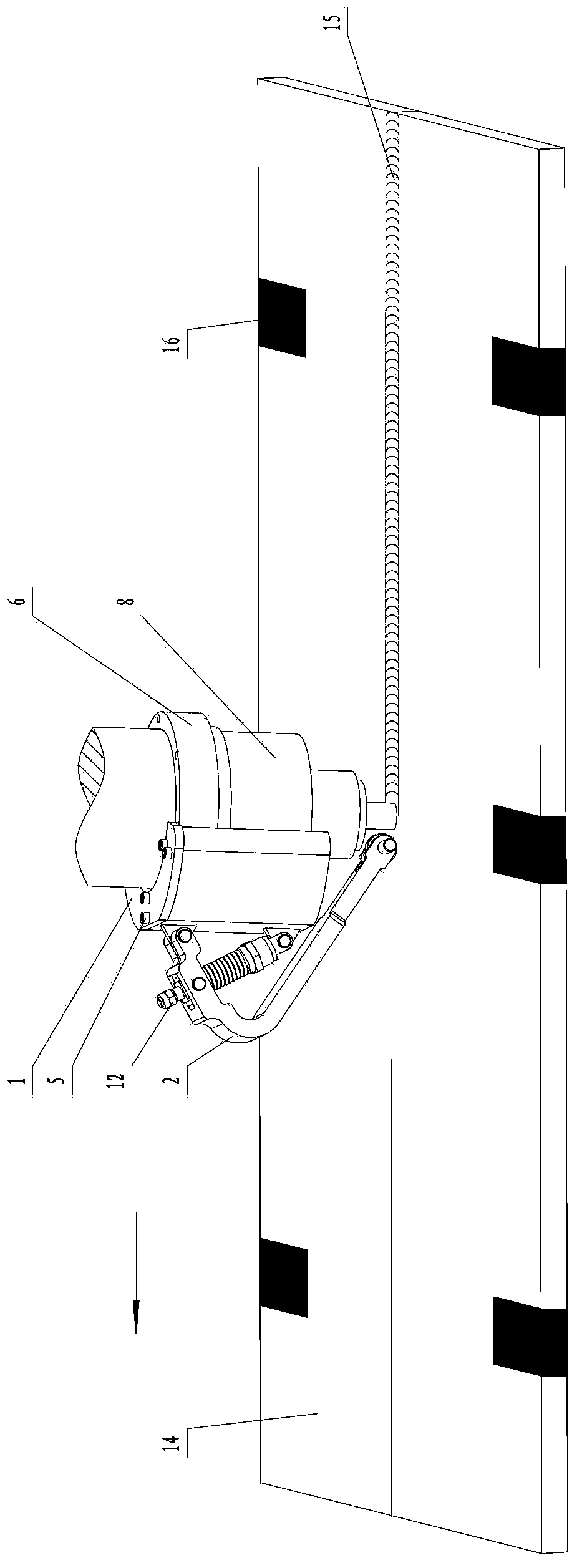
[0023] Such as figure 1 , figure 2 As shown, the extrusion device with welding of the present invention includes a support 1, a support arm 2, a force spring 3, an extrusion wheel 4, a nut 12 and a screw 13, and a static bushing 6 is installed on the main shaft 8 of the friction stir welding machine. The support 1 is fixed on the stationary shaft sleeve 6 through the first bolt 5 . The support arm 2 is "L"-shaped, with "U"-shaped grooves at both ends; one end of the support arm 2 is hinged on the support 1 through the first pin shaft 7, and the other end is equipped with a squeeze wheel 4. The wheel 4 is located in the "U" groove at the other end of the support arm 2 and is rotatable; the main shaft 8 is equipped with a welding tool 9 with a stirring pin 11, and the extrusion wheel 4 is located in front of the stirring pin 11 in the welding direction. On ...


PUM

PropertyMeasurementUnit
Diameteraaaaaaaaaa

Abstract

The invention belongs to the field of friction stir welding and particularly relates to a welding with trailing extrusion device for friction stir welding and a welding with trailing extrusion method thereof. The device comprises a supporting base, a supporting arm, a force applying spring and an extruding wheel, wherein the supporting base is connected with a static shaft sleeve of a friction stir welder through a bolt, so that the device is welded to the welder; the supporting arm is L-shaped; the supporting arm and the force applying spring are connected with the supporting base through pin shafts; the extruding wheel is connected to the tail end of the L-shaped supporting arm, and moves downwards through a main shaft to stress a to-be-welded workpiece. When the welding with trailing extrusion device is used for welding a metal plate which is relatively large or small in width, the manufacturing cost of a clamping tool can be effectively reduced, the process of mounting the clamping tool before welding is simplified, the welding space of a welding tool is increased, high-quality formation of a welding seam is guaranteed, and the application range of friction stir welding technology is widened.

Description

technical field [0001] The invention belongs to the field of friction stir welding, in particular to a welding extrusion device and welding extrusion method for friction stir welding. Background technique [0002] Friction stir welding is a new solid-phase joining technology developed by the British Welding Institute (TWI) in 1991. Compared with traditional fusion welding methods, it has the advantages of high quality, low cost, low deformation and no pollution to the environment; Therefore, since its invention, it has been successfully used in the fields of aerospace, aviation, automobiles and ships. In the process of friction stir welding, a rigid backing plate is often placed at the bottom of the workpiece to be welded to support the workpiece by upsetting. The close contact between the workpiece being welded and the backing plate during welding is the key to obtaining a high-quality weld. In order to meet this requirement, the common practice is to implement rigid extr...

Claims


Application Information

Patent Timeline
IPC IPC(8): B23K20/12B23K20/26
CPCB23K20/122B23K20/26
Inventor 王敏杨广新张会杰张景宝张骁武加锋
Owner SHENYANG INST OF AUTOMATION - CHINESE ACAD OF SCI
Learn More