
Raw material mixing device for coating production

A mixing device and raw material technology, applied in mixers, mixers with rotating stirring devices, transportation and packaging, etc., can solve the problems of difficult cleaning of raw materials, influence of coating performance, easy pilling of raw materials, etc., to reduce pilling of raw materials , Improve the quality, improve the mixing effect

Inactive Publication Date: 2020-10-16
马恒
View PDF0 Cites 0 Cited by
  • Summary
  • Abstract
  • Description
  • Claims
  • Application Information

AI Technical Summary

Problems solved by technology

[0003] In the process of mixing the raw materials of the paint in the existing paint production equipment, the raw materials are prone to pilling, resulting in uneven mixing, and a large amount of raw materials are attached to the inner wall, resulting in a change in the ratio, which has a certain impact on the performance of the paint, and It is difficult to clean the raw materials attached to the inner wall of the shell

Method used


Image

  • Raw material mixing device for coating production
  • Raw material mixing device for coating production
  • Raw material mixing device for coating production

Examples


Embodiment 1

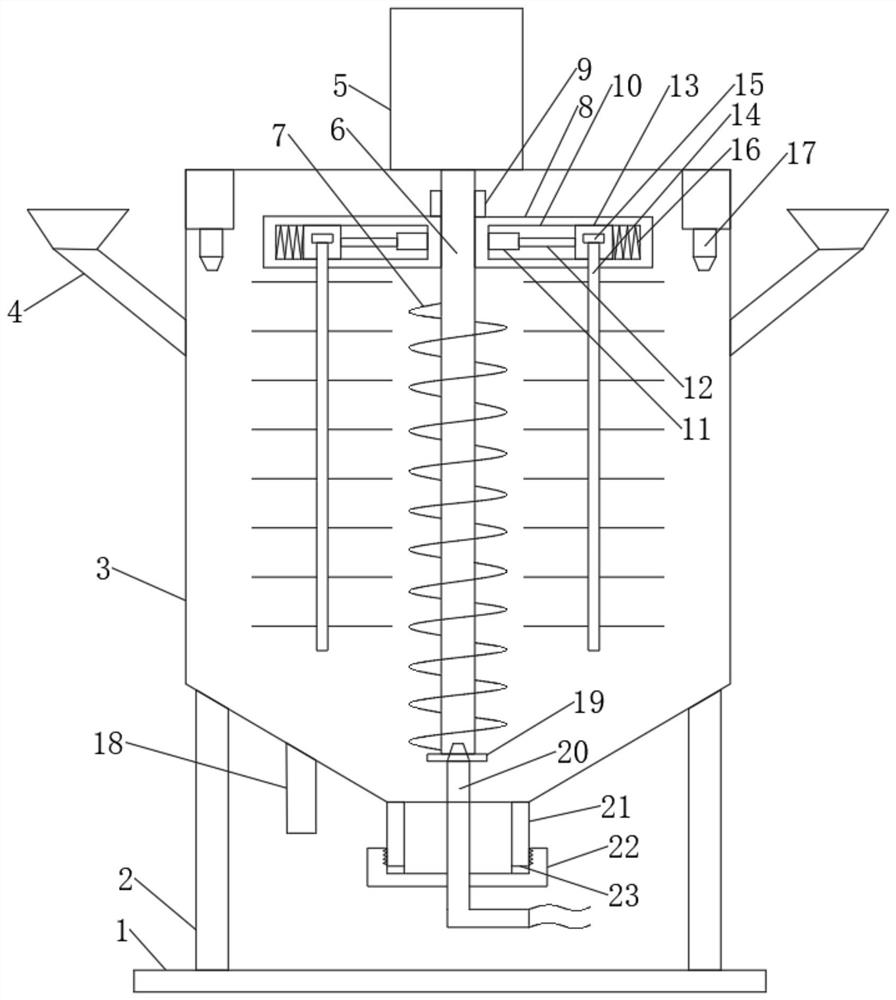
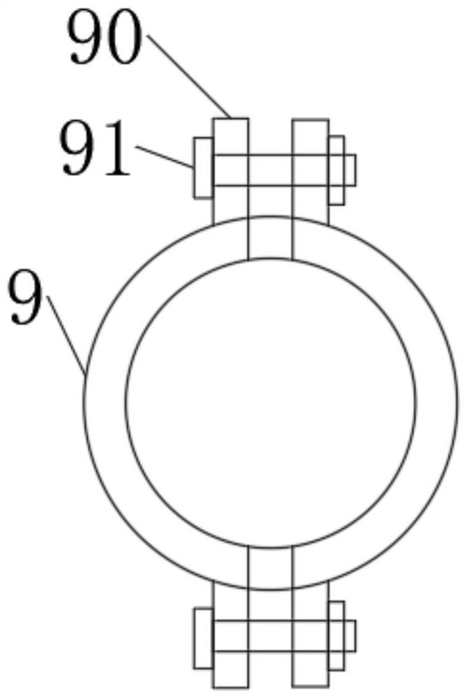
[0025] Such as Figure 1-4 As shown, a raw material mixing device for paint production includes a base 1, a column 2 is arranged on the base 1, the column 2 is connected with a housing 3, and two feeding hoppers are symmetrically arranged on the housing 3 4. The top of the housing 3 is provided with a first motor 5, the first motor 5 is connected to the output shaft 6, the output shaft 6 is rotatably installed in the center of the housing 3, and the output shaft 6 is set Stirring blade 7 is arranged, and described output shaft 6 is provided with installation frame 8, and described installation frame 8 is connected with output shaft 6 through fixed block 9, and described fixed block 9 is symmetrically distributed on both sides of output shaft 6, and described fixed block 9 The block 9 is provided with fixing flanges 90, and fixing bolts 91 are arranged between the fixing flanges 90, and a mounting groove 10 is arranged in the mounting bracket 8, and a second motor 11 is arrange...

Embodiment 2

[0040] This embodiment is a further improvement and limitation of embodiment 1 on the basis of embodiment 1.

[0041] A raw material mixing device for coating production, including all parts in embodiment 1, also includes:

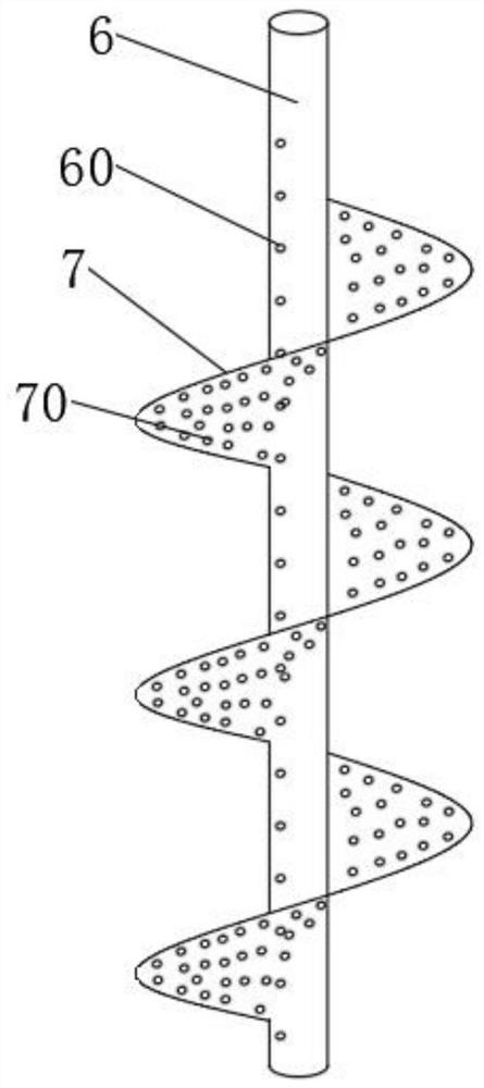
[0042] Further, the bottom of the housing 3 is provided with a connecting sleeve 21, the connecting sleeve 21 is connected with a threaded sleeve 22, and the threaded sleeve 22 is provided with a water pipe 20, and the water pipe 20 passes through the first rubber The pad 19 is connected with the bottom of the output shaft 6 , the output shaft 6 is hollow, and the output shaft 6 is uniformly provided with water outlet holes 60 .

[0043] Specifically, since the water at the output shaft 6 is not easy to reach, by connecting the water pipe 20 at the bottom of the output shaft 6 and evenly setting the water outlet holes 60 on the output shaft 6, the water is introduced into the raw materials to improve the stirring effect and reduce the stirring effect. tim...


PUM


Abstract

The invention discloses a raw material mixing device for coating production, relates to the technical field of coating mixing, and mainly solves the problems that in the existing coating mixing process, mixing is not uniform, and raw materials are easily attached to the inner wall. The device comprises a base, a stand column is arranged on the base. The stand column is connected with the shell, wherein a feeding hopper is arranged on the shell; a first motor is arranged at the top of the shell; the first motor is connected with an output shaft; the output shaft and the center of the shell arerotationally installed. Stirring blades are arranged on the output shaft; a mounting frame is arranged on the output shaft; a mounting groove is formed in the mounting frame, a second motor is arranged in the mounting groove, the second motor is connected with an ejector rod, the ejector rod is connected with a sliding block, a stirring rod is connected to the sliding block, stirring brushes are evenly arranged on the stirring rod, spray heads are arranged on the two sides of the shell, and a discharging pipe is arranged at the bottom of the shell.

Description

technical field [0001] The invention relates to the technical field of paint production, in particular to a raw material mixing device for paint production. Background technique [0002] Paint, traditionally known as paint in China. The so-called paint is coated on the surface of the object to be protected or decorated, and can form a continuous film firmly attached to the object to be coated, usually based on resin, oil, or emulsion, with or without adding pigments, fillers, adding Corresponding additives are liquids prepared with organic solvents or water. During the production of coatings, it is necessary to use raw material mixing and stirring equipment to mix the various raw materials added in the coating production process evenly. [0003] In the process of mixing the raw materials of the paint in the existing paint production equipment, the raw materials are prone to pilling, resulting in uneven mixing, and a large amount of raw materials are attached to the inner wa...

Claims


Application Information

Patent Timeline
Patent Type & Authority Applications(China)
IPC IPC(8): B01F7/24B01F7/18B01F15/00B01F15/02
CPCB01F27/1141B01F27/17B01F27/213B01F27/2312B01F27/2322B01F27/805B01F27/191B01F27/85B01F27/9214B01F27/90B01F35/121B01F35/323B01F35/3231B01F35/3215B01F35/3204B01F35/43B01F35/7164B01F35/71731B01F35/7179B01F2101/30
Inventor 马恒
Owner 马恒
Learn More