
Bearing lubrication structure for screw blower or vacuum pump

A bearing lubrication and blower technology, which is applied to the components, pumps, and pump elements of the pumping device for elastic fluids, can solve the problems of occupying the axial length space of the bearing, occupied, and multi-bearing axial space, etc. The effect of small space occupation, convenient manufacture and compactness

Active Publication Date: 2020-10-09
浙江珂勒曦动力设备股份有限公司
View PDF6 Cites 0 Cited by
  • Summary
  • Abstract
  • Description
  • Claims
  • Application Information

AI Technical Summary

Problems solved by technology

[0005] The existing technical solutions above have the following defects: before the lubricating oil enters the bearing, an oil supply channel must be provided in front of the bearing end, which will occupy the axial length of the bearing, and the oil collection ring will also occupy the axial length of the bearing space; the bearing lubrication structure occupies more space in the axial direction of the bearing, which is not conducive to the compactness and miniaturization of the product

Method used


Image

  • Bearing lubrication structure for screw blower or vacuum pump
  • Bearing lubrication structure for screw blower or vacuum pump
  • Bearing lubrication structure for screw blower or vacuum pump

Examples


Embodiment 1

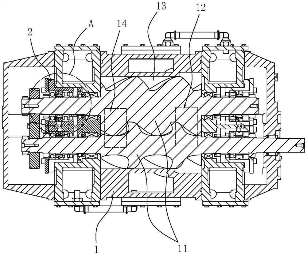
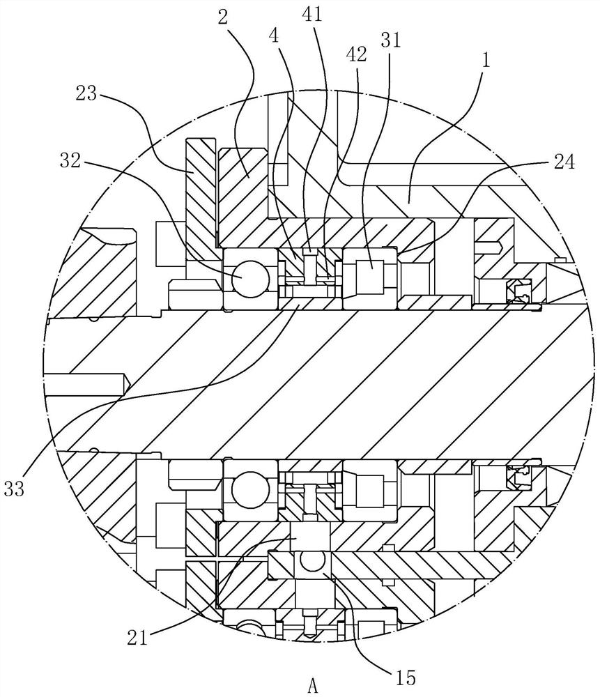
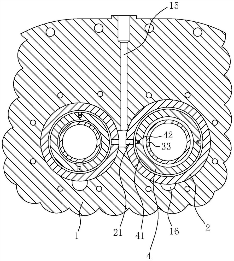
[0038] refer to figure 1 , is a bearing lubricating structure of a screw blower or a vacuum pump disclosed by the present invention, including a casing 1 and a bearing seat 2. Two screws 11 are arranged in parallel in the casing 1, and the rotating shafts of the two screws 11 are at the same height. The number of bearing seats 2 corresponds to the number of ends of the screw rods 11 , and the rotating shafts of the screw rods 11 penetrate into the bearing seats 2 in a one-to-one correspondence. The casing 1 is provided with an air inlet 12, a compression chamber 13, and an exhaust port 14 that communicate with each other. The compression chamber 13 is a working chamber for the screw 11 to rotate. The length direction of the compression chamber 13 is along the length direction of the screw rod 11. The end of 13 is the position close to the exhaust port 14, which is the compression end of the screw 11. When the screw blower or vacuum pump is running, the end of the compression c...

Embodiment 2

[0048] A bearing lubrication structure for a screw blower or a vacuum pump, the difference between Embodiment 2 and Embodiment 1 is:

[0049] refer to Figure 6 , the casing 1 is provided with a sliding hole 17, the sliding hole 17 is located above the oil inlet hole 21, the sliding hole 17 connects the oil inlet passage 15 with the end area of ​​the compression chamber 13, the sliding hole 17 and the oil inlet passage 15 intersect to form a cross , the sliding hole 17 is provided with a spring 51 and a piston rod 52 for sliding, wherein the end of the piston rod 52 communicates with the compression chamber 13, the spring 51 is located on the side of the piston rod 52 away from the compression chamber 13, and the spring 51 is located in the sliding hole 17 bottom of the hole. The piston rod 52 establishes a sliding seal with the sliding hole 17 through the sealing ring. The side wall of the piston rod 52 is provided with a port 521 for oil supply to pass through. The sliding...


PUM


Abstract

The invention discloses a bearing lubrication structure for a screw blower or a vacuum pump, and relates to a lubrication structure. The key point of the technical scheme is as follows: the bearing lubrication structure comprises an enclosure and a bearing seat, wherein a first bearing is arranged in the bearing seat; an oil inlet channel and an oil outlet channel are arranged in the enclosure; anoil inlet communicating with the oil inlet channel and an oil collecting hole communicating with the oil outlet channel are formed in the bearing seat; an oil distributing ring is arranged in the bearing seat; a circular groove is formed in the outer ring wall of the oil distributing ring along a circumferential direction; the circular groove communicates with the oil inlet; a plurality of oil outlets are formed in the end face of the oil distributing ring; the oil outlets face the first bearing, and the oil outlets communicate with the annular groove; the oil inlet and the oil collecting hole are located at the same position in the axial direction of the first bearing, the oil distributing ring is provided with an oil-through groove closely to the oil collecting hole, the oil-through groove penetrates through the inner ring face of the oil distributing ring from the outer ring face of the oil distributing ring, and the oil collecting hole faces the oil-through groove. The bearing lubrication structure occupies less space in the axial direction of the bearing, which is conducive to the compactness and miniaturization of a product; and the disassembly, assembly and manufacturing ofthe bearing lubrication structure are more convenient.

Description

technical field [0001] The invention relates to a lubricating structure, in particular to a bearing lubricating structure of a screw blower or a vacuum pump. Background technique [0002] The screw blower is a device that uses a pair of screws to perform synchronous reverse rotation in the shell to generate exhaust. The working principle and structure of the screw vacuum pump are basically the same as the screw blower. The difference is that the exhaust port of the screw blower is used as the working end. , The suction port of the screw vacuum pump is used as the working end. A rotational connection is established between the screw and the housing through bearings, and the screw blower or vacuum pump is generally provided with a lubricating structure for lubricating the bearings. [0003] The Chinese invention patent application whose publication number is CN109139708A discloses a bearing lubricating structure. The bearing lubricating structure includes: a rotating shaft; a...

Claims


Application Information

Patent Timeline
Patent Type & Authority Applications(China)
IPC IPC(8): F04C18/16F04C25/02F04C29/02
CPCF04C18/16F04C25/02F04C29/02F04C2240/56
Inventor 许祖近刘永胜
Owner 浙江珂勒曦动力设备股份有限公司
Learn More