
Diaphragm pump and pump head structure thereof

A diaphragm pump and pump head technology, applied in the direction of pumps, pump components, variable capacity pump components, etc., to reduce reciprocating fatigue wear, improve water flow and work efficiency, and improve volume utilization.

Pending Publication Date: 2020-10-02
A O SMITH CHINA WATER HEATER CO LTD +1
View PDF0 Cites 0 Cited by
  • Summary
  • Abstract
  • Description
  • Claims
  • Application Information

AI Technical Summary

Problems solved by technology

[0004] However, in the case of a certain internal space of the water purification system, it can only be installed with a diaphragm pump with a predetermined water flow rate.

Method used


Image

  • Diaphragm pump and pump head structure thereof
  • Diaphragm pump and pump head structure thereof
  • Diaphragm pump and pump head structure thereof

Examples


Embodiment Construction

[0047] The technical solutions of the present invention will be described in detail below with reference to the accompanying drawings and specific embodiments. It should be understood that these embodiments are only used to illustrate the present invention and not to limit the scope of the present invention. Various equivalent modifications of the invention are intended to fall within the scope defined by the claims appended hereto.

[0048] It should be noted that when an element is referred to as being "disposed on" another element, it can be directly on the other element or intervening elements may also be present. When an element is referred to as being "connected" to another element, it can be directly connected to the other element or intervening elements may also be present. The terms "vertical", "horizontal", "upper", "lower", "left", "right" and similar expressions used herein are for the purpose of illustration only and do not represent the only embodiment.

[0049]...


PUM


Abstract

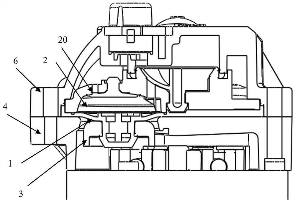
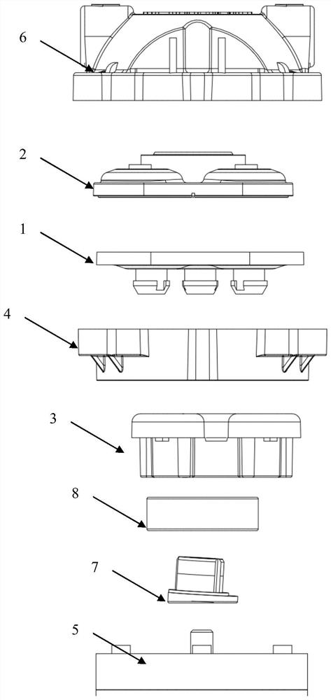
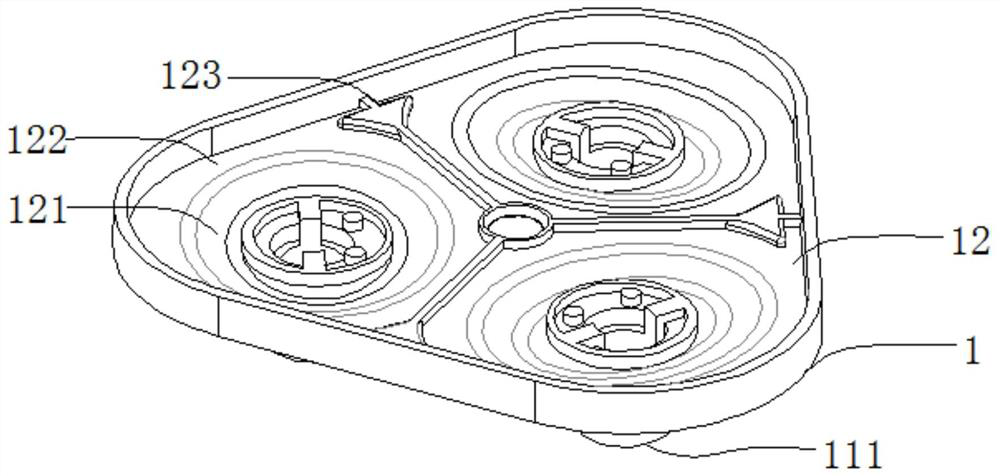
The invention discloses a diaphragm pump and a pump head structure thereof. The pump head structure comprises a transmission head, a diaphragm and a valve seat which are sequentially arranged in the direction of an output shaft of a motor, and the diaphragm is provided with a first surface matched with the transmission head and a second surface matched with the valve seat; a plurality of wading parts capable of making contact with fluid are arranged on the second surface, a pressurizing cavity is formed between each wading part and the valve seat, and the area ratio of the wading parts to thediaphragm is 50%-70%. According to the diaphragm pump and the pump head structure thereof, parameters such as the water outlet flow and the working efficiency of the diaphragm pump can be improved under the condition that it is guaranteed that the size of the diaphragm pump is not changed and the structural durability is good, and therefore the requirements of users for high performance, low cost,low noise, small size and the like of the diaphragm pump are met.

Description

technical field [0001] The invention relates to the technical field of diaphragm pumps, in particular to a diaphragm pump and a pump head structure thereof. Background technique [0002] Diaphragm pumps are mechanical structures that deliver liquids or pressurize liquids through a diaphragm. The existing diaphragm pump can use a reciprocating drive member to drive the diaphragm to deform to achieve the purpose of sucking liquid; it can also be driven by a driving member such as a nutating disc or a swinging disc to drive the diaphragm to deform to achieve the purpose of suctioning liquid. Diaphragm pumps are widely used in water purification and other industries. [0003] At present, the diaphragm pumps provided by manufacturers are largely standardized into several fixed models. Different types of diaphragm pumps correspond to parameters such as predetermined water flow and fixed volume. In general, the larger the water flow of the diaphragm pump, the larger its volume. ...

Claims


Application Information

Patent Timeline
Patent Type & Authority Applications(China)
IPC IPC(8): F04B43/04F04B53/00F04B53/10
CPCF04B43/0054F04B43/04F04B53/00F04B53/001F04B53/10
Inventor 王震蒋万明洪峰
Owner A O SMITH CHINA WATER HEATER CO LTD
Learn More