Solid electrolytic capacitor

一种固体电解、电容器的技术,应用在固体电解电容器、电解电容器、电容器等方向,能够解决制造工艺复杂化、电容有效体积变小、金属箔不具有电容器功能等问题,达到可靠性优异、容易廉价制作的效果

Active Publication Date: 2020-09-29
MURATA MFG CO LTD
View PDF11 Cites 0 Cited by
  • Summary
  • Abstract
  • Description
  • Claims
  • Application Information

AI Technical Summary

Problems solved by technology

However, since this metal foil does not function as a capacitor, it becomes the cause of the reduction in the capacitance effective volume occupied by the entire product.
In addition, in order to manufacture the solid electrolytic capacitor described in Patent Document 1, it is necessary to process the metal foil, so the manufacturing process tends to become complicated.

Method used


Image

  • Solid electrolytic capacitor
  • Solid electrolytic capacitor
  • Solid electrolytic capacitor

Examples


no. 1 approach

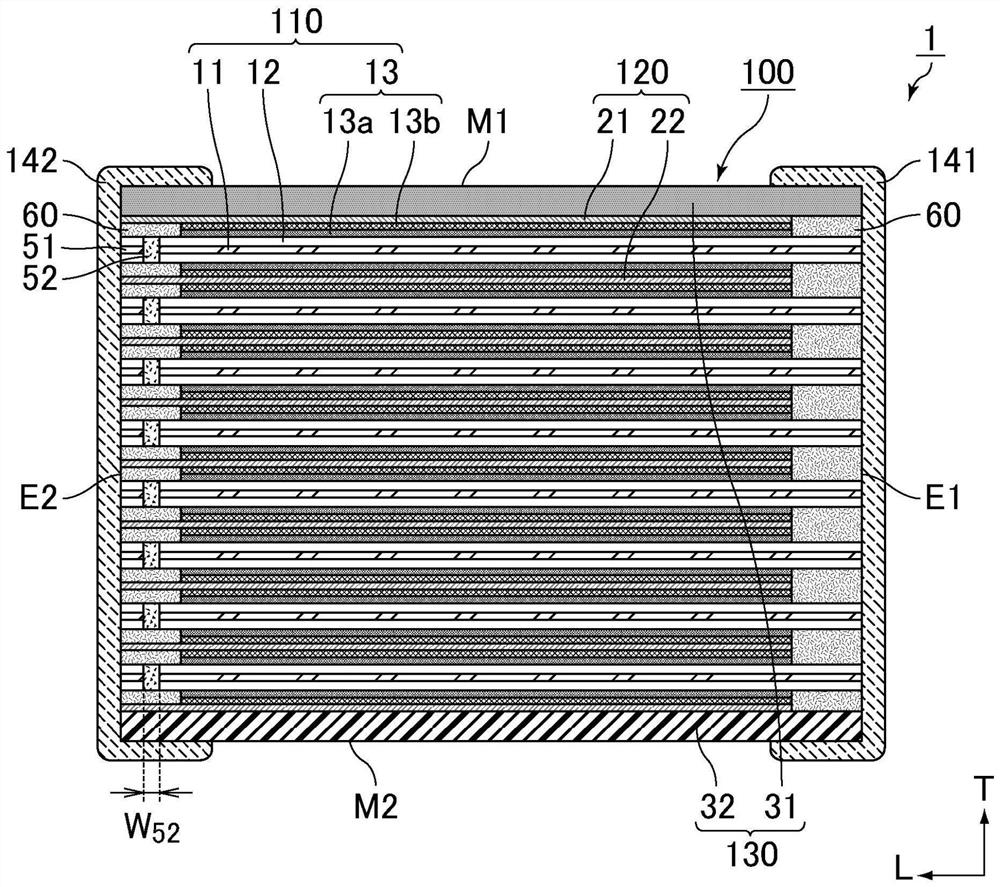
[0078] In the solid electrolytic capacitor according to the first embodiment of the present invention, the metal foil exposed on the second end surface of the element laminate is provided in a space where there is no capacitor element between the first cathode extraction layer and the second cathode extraction layer. . The above-mentioned metal foil is cut from the anode foil through a slit, and is completely insulated from the anode foil.

[0079] In the solid electrolytic capacitor according to the first embodiment of the present invention, the metal foil cut off from the anode foil is directly used as a support portion of the cathode lead-out layer. Thereby, no difference in the coefficient of linear expansion occurs, and structural deformation, generation of cracks, and the like can be suppressed when heat is applied to the solid electrolytic capacitor.

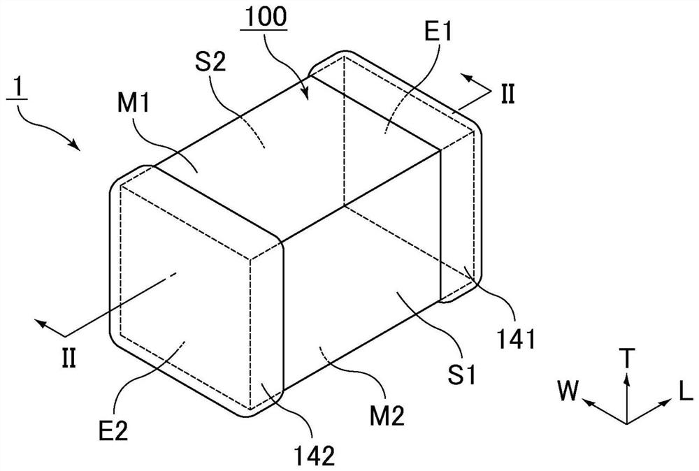
[0080] figure 1 It is a perspective view schematically showing an example of the solid electrolytic capacitor accordi...

no. 2 approach

[0130] In the solid electrolytic capacitor according to the second embodiment of the present invention, an insulating layer is provided to fill the space without the capacitor element between the first cathode extraction layer and the second cathode extraction layer.

[0131] In the solid electrolytic capacitor according to the second embodiment of the present invention, the insulating layer may be made of a different insulating material from the resin molded body, or may be made of the same insulating material as the resin molded body.

[0132] When the insulating layer is made of an insulating material different from the resin molded body, by selecting the insulating material constituting the insulating layer, the insulating layer can be provided with functions for improving reliability, such as a function of low moisture permeability, a stress Mitigation capabilities, etc.

[0133] On the other hand, when the insulating layer is made of the same insulating material as the r...


PUM


Abstract

The invention provides a solid electrolytic capacitor which is easy to manufacture at low cost, has a low-resistance structure and is excellent in reliability. The solid electrolytic capacitor that includes a capacitor element laminate, a first external electrode, and a second external electrode. The capacitor element laminate includes capacitor elements, cathode lead-out layers, and a sealing body. At least one capacitor element includes an anode foil, dielectric layers, and cathode layers. The first external electrode is connected to the anode foil exposed at the first end surface of the capacitor element laminate. The second external electrode is connected to the cathode lead-out layers exposed at the second end surface of the capacitor element laminate. A first cathode lead-out layer and a second cathode lead-out layer are both conductive paste layers, and uniformly extend from where the first cathode lead-out layer and the second cathode lead-out layer are disposed on the cathodelayers to the second external electrode.

Description

technical field [0001] This invention relates to solid electrolytic capacitors. Background technique [0002] Patent Document 1 discloses a solid electrolytic capacitor in which a plurality of units are laminated, and the unit has: a valve metal substrate having a porous layer on the surface; a dielectric layer formed on the surface of the porous layer; and a solid electrolyte layer , disposed on the above-mentioned dielectric layer, the solid electrolytic capacitor is characterized in that there are conductor layers between the stacked units, at least one of the above-mentioned conductor layers includes a metal foil, and the above-mentioned units and the above-mentioned conductor layers are covered with an exterior resin For sealing, the anode side end surface of the above-mentioned valve action metal substrate is directly connected to the anode external electrode formed on the surface of the exterior resin on one end surface of the solid electrolytic capacitor, and the abo...

Claims


Application Information

Patent Timeline
Patent Type & Authority Applications(China)
IPC IPC(8): H01G9/012H01G9/042H01G9/15
CPCH01G9/15H01G9/012H01G9/0425H01G9/048H01G2009/05H01G9/14H01G9/26
Inventor 古川刚史玉谷康浩
Owner MURATA MFG CO LTD
Why Eureka
Try Eureka