
A hardware component cleaning device

A cleaning device and component technology, applied in cleaning methods and tools, cleaning methods using liquids, chemical instruments and methods, etc., can solve problems such as leaving gaps in hardware structures, single ultrasonic treatment for cleaning structural frame grooves, and interference with cleaning quality, etc. , to achieve the effect of ensuring cleanliness

Active Publication Date: 2021-05-14
保定永展电子设备制造有限公司
View PDF7 Cites 0 Cited by
  • Summary
  • Abstract
  • Description
  • Claims
  • Application Information

AI Technical Summary

Problems solved by technology

[0004] Aiming at the deficiencies in the prior art, the object of the present invention is to provide a cleaning device for hardware components to solve the problem that the ultrasonic vibration cleaning of hardware needs rigid collision to form the decontamination effect of roller noise reduction and vibrating screen, but the internal chamfer groove of the hardware thread The interstitial pollutants are viscous dust blocks, which can easily affect the plugging pad support of the thread pitch when the cleaning is not complete in the later stage, resulting in gaps in the hardware structure and uneven alveoli, resulting in repeated ultrasonic vibration cleaning operations, making the thread pitch of the hardware susceptible to damage. High-intensity collisions produce internal pressure deformation, resulting in a single ultrasonic treatment for cleaning the structural frame grooves, and weakening the anti-shock efficiency of acoustic waves, which interferes with the cleaning quality

Method used


Image

  • A hardware component cleaning device
  • A hardware component cleaning device
  • A hardware component cleaning device

Examples


Embodiment 1

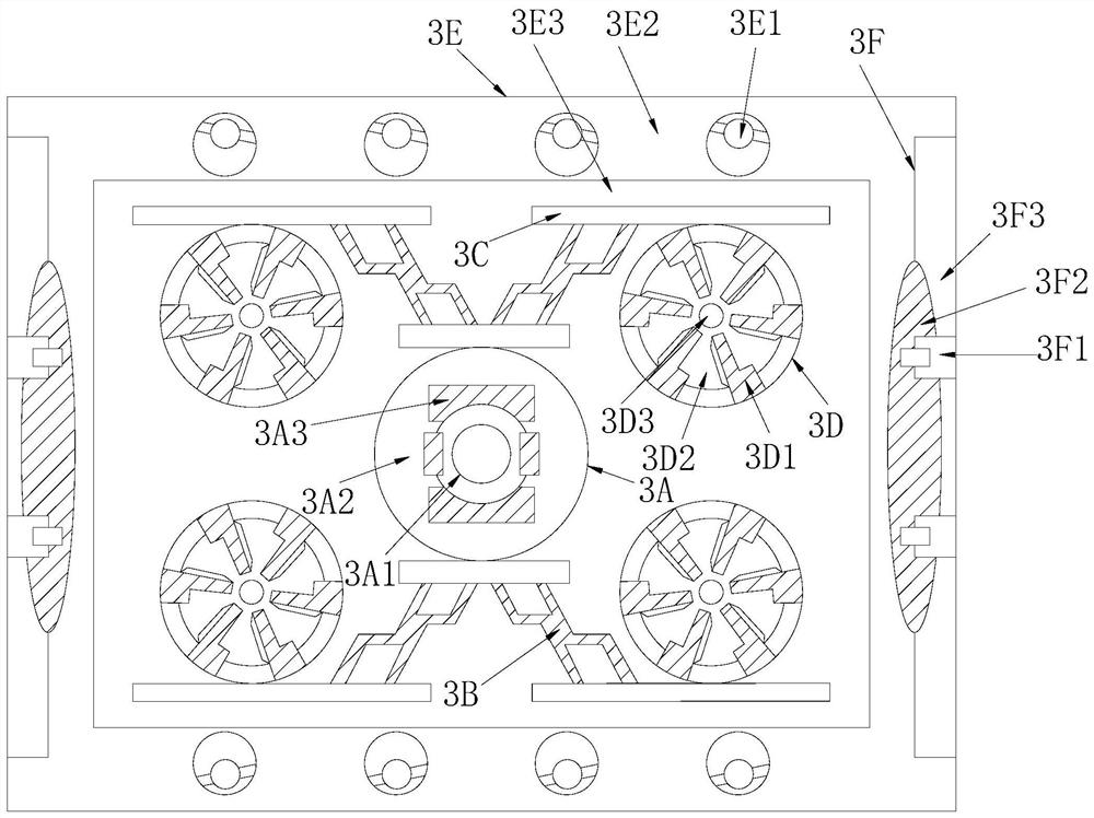
[0033] see Figure 1-Figure 6, the invention provides a cleaning device for hardware components, the structure of which includes: an aluminum shell square groove 1, a top cover plate 2, an inner groove of a vortex vibrating screen 3, an electric control panel 4, a facade baffle 5, a switch valve handle 6, a row The flow tube 7, the inner tank 3 of the vortex vibrating screen is installed in the square tank 1 of the aluminum shell, the electric control panel 4 is installed in the upper right corner of the square tank 1 of the aluminum shell, and the top cover plate 2 is nested in the vortex vibrating screen. On the top of the screen inner tank 3, the facade baffle plate 5 is closely attached to the square tank 1 of the aluminum shell and is on the same vertical plane, and the drain pipe 7 is inserted in the lower left corner of the square tank 1 of the aluminum shell And communicate with each other, the switch valve handle 6 is mechanically connected with the inner groove 3 of ...

Embodiment 2

[0040] see Figure 1-Figure 6 , the present invention provides a hardware component cleaning device, other aspects are the same as in Embodiment 1, the difference is:

[0041] see figure 2 , the ultrasonic cushion 3F is composed of a sound wave generator 3F1, a flat ellipsoid 3F2, and a foam sound insulation board 3F3, and the flat ellipsoid 3F2 is nested on the left side of the foam sound insulation 3F3 and is on the same vertical plane Above, the sound wave generator 3F1 is embedded in the flat ellipsoid 3F2, and the sound wave generator 3F1 is inserted into the flat ellipsoid 3F2 to form the horizontal output of longitudinal air pressure to ensure the quality of ultrasonic waves and the frequency conversion of electronic control. operate.

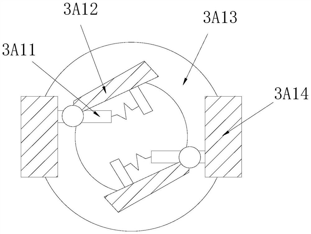
[0042] see Figure 6 , the acoustic wave generator 3F1 is composed of a converging tube groove 3F11, a casing block 3F12, a cyclone inner chamber 3F13, and a photoelectric resonance tube 3F14, and the converging tube groove 3F11 is i...


PUM


Abstract

The invention discloses a cleaning device for hardware components, the structure of which comprises: an aluminum shell square groove, a top cover plate, an inner groove of a vortex vibrating screen, an electric control panel, a facade baffle, a switch valve handle, and a drainage pipe. In order to use the square groove of the aluminum shell to cooperate with the inner groove of the vortex vibrating screen, the floor drain suction operation is formed as a whole by using the square groove of the aluminum shell to pack the liner groove and the ultrasonic pad to connect the eddy current brush wheel, so that the fluid pulls the hardware The viscous impurities in the thread clamping groove form a pulling and swirling scraping, so that the fluid pressure cooperates with the ultrasonic corrugated vibrating screen to form a grid-type base pumping fluidized bed composite cleaning effect, ensuring the immersion and water washing of the stacked hardware components in the groove plate The rotary brush can effectively improve the negative pressure vortex operation of external structure cleaning and internal thread rotary flushing, so that the overall hardware can cooperate with the ultrasonic vibrating screen and the circulating water flow to form an increased feedback acoustic shock effect, improving the effect of ultrasonic transmission and reception.

Description

technical field [0001] The invention relates to a cleaning device for hardware components, which belongs to the field of hardware. Background technique [0002] The cleaning of hardware parts requires the combination of ultrasonic and water washing on the dust on the surface and the rust on the inner chamfer, so as to ensure the fluid wrapping of the hardware components and the feedback operation of the sound wave transmission of the water level medium during the vibrating screen process, so as to obtain the quality effect of cleaning and renovation, and use mechanical cleaning Instead of manual cleaning labor, the equipment can be operated more efficiently. The disadvantages of the current technology that need to be optimized are: [0003] The ultrasonic vibration cleaning of hardware needs rigid collision to form the decontamination effect of roller noise reduction and vibrating sieve, but the gap pollutants in the internal chamfer groove of hardware threads are sticky dus...

Claims


Application Information

Patent Timeline
Patent Type & Authority Patents(China)
IPC IPC(8): B08B3/12B08B3/10B08B3/04
CPCB08B3/047B08B3/102B08B3/12
Inventor 黄碧芳
Owner 保定永展电子设备制造有限公司
Learn More