Particle radiation therapy apparatus
A treatment device and particle beam technology, which is applied in the fields of treatment, radiation detection device, X-ray/γ-ray/particle irradiation therapy, etc.
- Summary
- Abstract
- Description
- Claims
- Application Information
AI Technical Summary
Problems solved by technology
Method used
Image
Examples
no. 1 approach
[0025] Embodiments of the present invention will be described below based on the drawings.
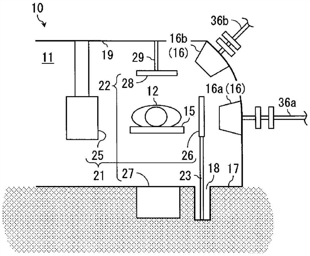
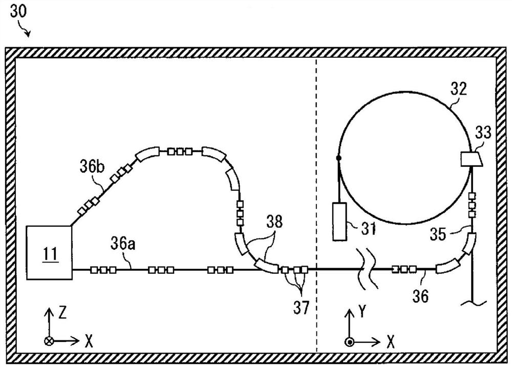
[0026] figure 1 It is a figure showing the treatment room 11 provided with the particle beam therapy apparatus 10 of 1st Embodiment. In this way, the particle beam therapy apparatus 10 includes: the bed 15 that moves in the space of the treatment room 11 to position the patient 12; 36b) The transported particle beam; the horizontal direction imaging unit 21 is composed of the first X-ray source 25 and the first X-ray detector 26 facing each other across the bed 15 along the horizontal line; the vertical direction imaging unit 22, It is composed of a second X-ray source 27 and a second X-ray detector 28 opposed to each other across the bed 15 along a vertical line; the storage room 18 is arranged on the ground side 17 of the treatment room 11, and the horizontal direction is not used. The first X-ray detector 26 is stored under the ground during the imaging unit 21; The imaging unit ...
no. 2 approach
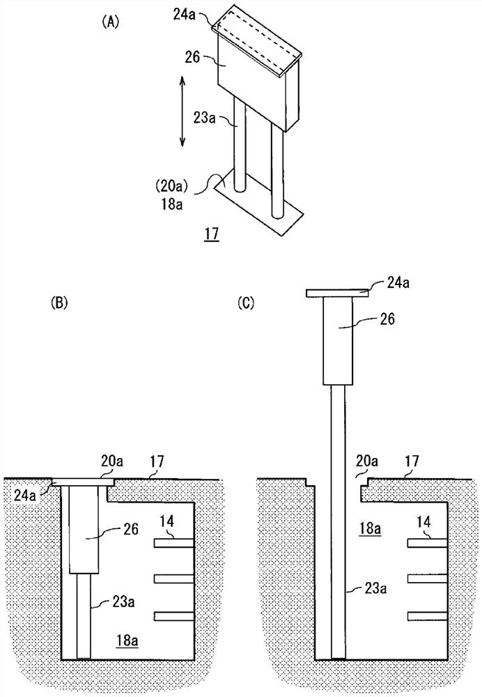
[0065] Next, refer to Figure 4 A second embodiment of the present invention will be described. In the second embodiment, the overall configuration other than the X-ray detector of the horizontal direction imaging unit is the same as that of the first embodiment, and thus redundant description will be omitted.
[0066] Figure 4 (A) is a perspective view of an X-ray detector applied to the horizontal imaging unit of the particle beam therapy apparatus according to the second embodiment. Figure 4 (B) is a vertical cross-sectional view showing a state in which the X-ray detector is stored in the storage room. Figure 4 (C) is a longitudinal sectional view showing the state of the X-ray detector in use.
[0067] In the particle beam therapy apparatus according to the second embodiment, the second support for supporting the X-ray detector 26 and making it rotate and displace in the direction along the detection surface is provided in the storage room 18b provided on the ground...
no. 3 approach
[0071] Next, refer to Figure 5 A third embodiment of the present invention will be described. In the third embodiment, the overall configuration other than the X-ray detector of the horizontal direction imaging unit is the same as that of the first embodiment, and thus redundant description will be omitted.
[0072] Figure 5 (A) is a perspective view of the X-ray detector applied to the horizontal imaging unit of the particle beam therapy apparatus according to the third embodiment. Figure 5 (B) is a vertical cross-sectional view showing a state in which the X-ray detector is stored in the storage room. Figure 5 (C) is a vertical cross-sectional view showing a state in which an X-ray detector is used.
[0073] In the particle beam therapy apparatus according to the third embodiment, a third support member that supports the X-ray detector 26 and rotates and displaces it in a direction perpendicular to the detection surface is provided in the storage room 18c provided on ...
PUM
 Abstract
Description
Claims
Application Information
 - R&D Engineer
- R&D Manager
- IP Professional
- Industry Leading Data Capabilities
- Powerful AI technology
- Patent DNA Extraction
Browse by: Latest US Patents, China's latest patents, Technical Efficacy Thesaurus, Application Domain, Technology Topic, Popular Technical Reports.
© 2024 PatSnap. All rights reserved.Legal|Privacy policy|Modern Slavery Act Transparency Statement|Sitemap|About US| Contact US: help@patsnap.com


