Large-divergence-angle laser coupling single-mode optical fiber device and method

A single-mode optical fiber and large divergence technology, applied in the field of optical fiber, can solve the problems of inability to use laser, waste of equipment, and extremely high processing requirements

Pending Publication Date: 2020-09-25
珠海市运泰利自动化设备有限公司
View PDF1 Cites 1 Cited by
  • Summary
  • Abstract
  • Description
  • Claims
  • Application Information

AI Technical Summary

Problems solved by technology

However, this solution has extremely high requirements for the processing of the instrument. The focal length of the collimator alone reaches 5m, resulting in the size of the overall device being more than 5m. The equipment for auxiliary alignment must be left in the coupling optical path after use, resulting in Waste of equipment, etc.
Therefore, it is difficult to apply to the industrial field
And it is only suitable for coupling the quasi-parallel light emitted from the laser, and cannot be applied to the laser with a large divergence angle emitted from the semiconductor chip

Method used


Image

  • Large-divergence-angle laser coupling single-mode optical fiber device and method
  • Large-divergence-angle laser coupling single-mode optical fiber device and method
  • Large-divergence-angle laser coupling single-mode optical fiber device and method

Examples


Embodiment Construction

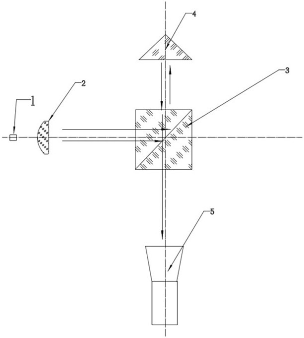
[0032] Such as Figure 1 to Figure 5 As shown, the present invention will be described in more detail below in conjunction with the accompanying drawings.

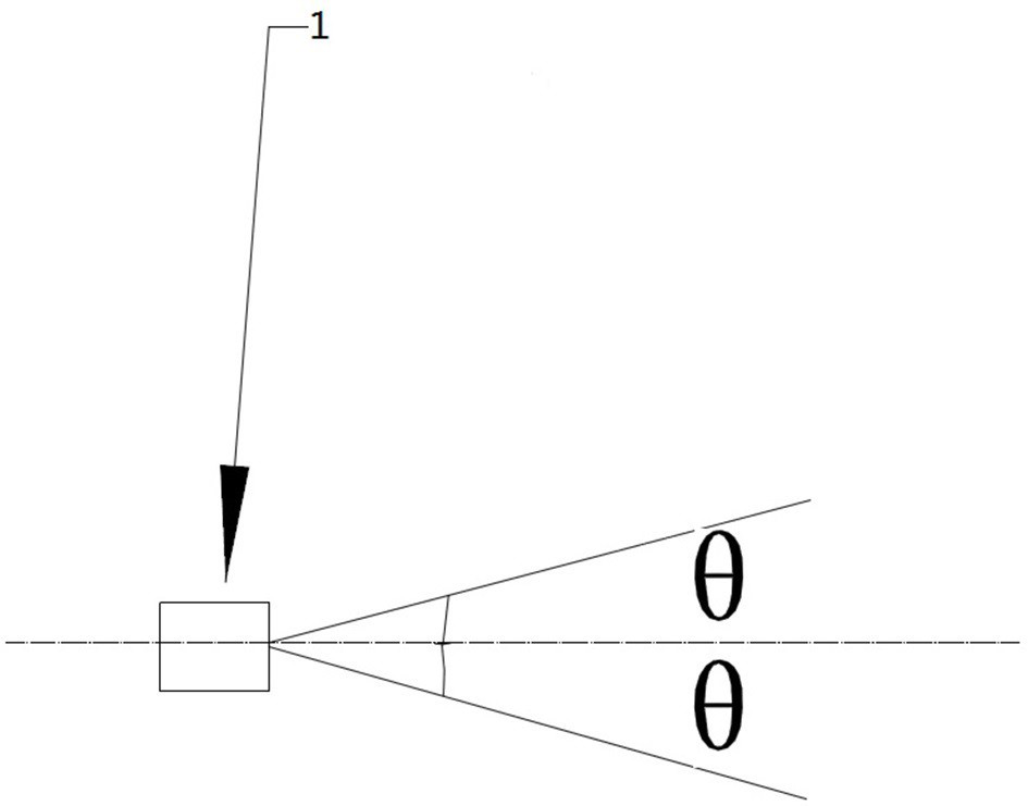
[0033] Such as figure 1 The laser 1 to be coupled into the fiber is shown. The divergence angle of the laser is 2θ, and the dotted line in the figure represents the optical axis.

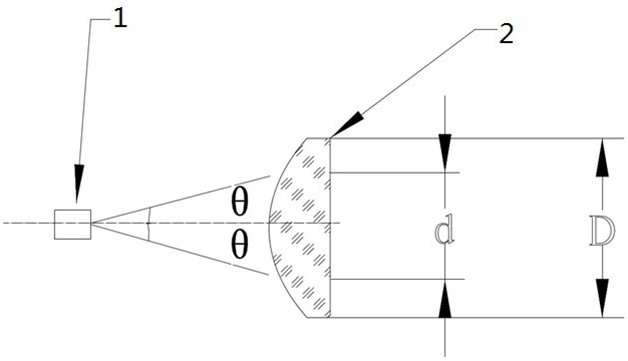
[0034] Such as figure 2 As shown, the light-emitting surface of the laser 1 is placed on the object focus of the collimator lens 2, and the focal length of the collimator lens 2 is set to f 1 , The RMS value of wave aberration should be less than 1 / 10λ, where λ is the incident light wavelength. In this embodiment, an aspheric lens is used. The clear surface needs to be coated with an anti-reflection coating adapted to the working wavelength, and its effective clear aperture D needs to meet: . After collimation by the collimator lens, the laser becomes parallel light parallel to the optical axis, and the spot diameter d is . In this embodiment, an...


PUM


Abstract

The invention provides a large-divergence-angle laser coupling single-mode optical fiber device and method, wherein the device is simple in structure, small in size and capable of saving resources. According to the invention, light emitted by a laser device is collimated by a collimating mirror and then is divided into transmission light and reflection light through a beam splitter prism; the reflection light is incident to a pyramid prism and then is absorbed by an industrial camera to form a reference light spot after being reflected in the original path; the transmission light split by thebeam splitter prism enters a microscope objective, is converged and then enters optical fiber, the coupling end surface of the optical fiber reflects a part of the incident light, and the part of thereflection light returns to the beam splitter prism along the original path, is reflected by the reflecting surface of the beam splitter prism and then is absorbed by the industrial camera to form a coupling light spot; and when the coupling light spot is completely overlapped with the reference light spot, the optical fiber emitted by the laser device is coupled into the optical fiber, otherwise,the pose of the optical fiber is adjusted until the coupling light spot is completely overlapped with the reference light spot. The device and the method of the invention can be applied to the fieldof fibers.

Description

Technical field [0001] The invention relates to the field of optical fibers, and in particular to a device and method for coupling a single-mode optical fiber with a large divergence angle laser. Background technique [0002] Optical fiber and cable communication is the main transmission method of modern communication transmission systems. The development history of optical fiber and cable has only been ten or twenty years. It has undergone three upgrades: short-wavelength multi-mode optical fiber cable, long-wavelength multi-mode optical fiber cable and long-wavelength single-mode optical fiber cable . As a brand-new information transmission technology, optical fiber communication technology has become the main communication method of modern communication, almost replacing traditional copper cable communication technology, and plays a very important role in modern information networks. It has been used in many fields and industries. Application has become an important means to ...

Claims


Application Information

Patent Timeline
Patent Type & Authority Applications(China)
IPC IPC(8): G02B6/42
CPCG02B6/4204G02B6/4222G02B6/4296
Inventor 王灵光赖宣润黄丽芳王成坤
Owner 珠海市运泰利自动化设备有限公司
Why Eureka
Try Eureka