An Ultrasonic Vibration Device for Coaxial Ultrasonic Assisted Laser Shot Peening

An ultrasonic-assisted, laser peening technology, applied in the direction of fluid using vibration, can solve the problems of unfavorable fatigue strength, low energy utilization rate of temperature field, unfavorable material structure, etc., to promote dynamic recrystallization behavior and ensure spot overlap , low-cost effect

Active Publication Date: 2021-08-03
JIANGSU UNIV
View PDF9 Cites 0 Cited by
  • Summary
  • Abstract
  • Description
  • Claims
  • Application Information

AI Technical Summary

Problems solved by technology

This method obtains a smaller grain size than the traditional laser shot peening technology through the thermal-mechanical coupling effect, but it still has the following disadvantages: (1) High temperature has a great influence on the properties of the core material of the part, which is not conducive to the formation of external strength. Internally tough material structure; (2) The energy utilization rate of the temperature field is low and the cost is high; (3) Due to the prevention of high temperature damage, the laser temperature shot peening equipment is complex and expensive
The above method uses ultrasonic vibration to stir / shock the laser-induced molten pool to achieve microstructure, but has the following disadvantages: (1) There are many structural defects in the laser melting process and it is difficult to control, such as pores, cracks, etc.; (2) Residual tensile stress appears on the surface of the material after laser melting, which is not conducive to the improvement of fatigue strength

Method used


Image

  • An Ultrasonic Vibration Device for Coaxial Ultrasonic Assisted Laser Shot Peening

Examples


Embodiment Construction

[0023] The present invention will be further described below in conjunction with the accompanying drawings and specific embodiments, but the protection scope of the present invention is not limited thereto.

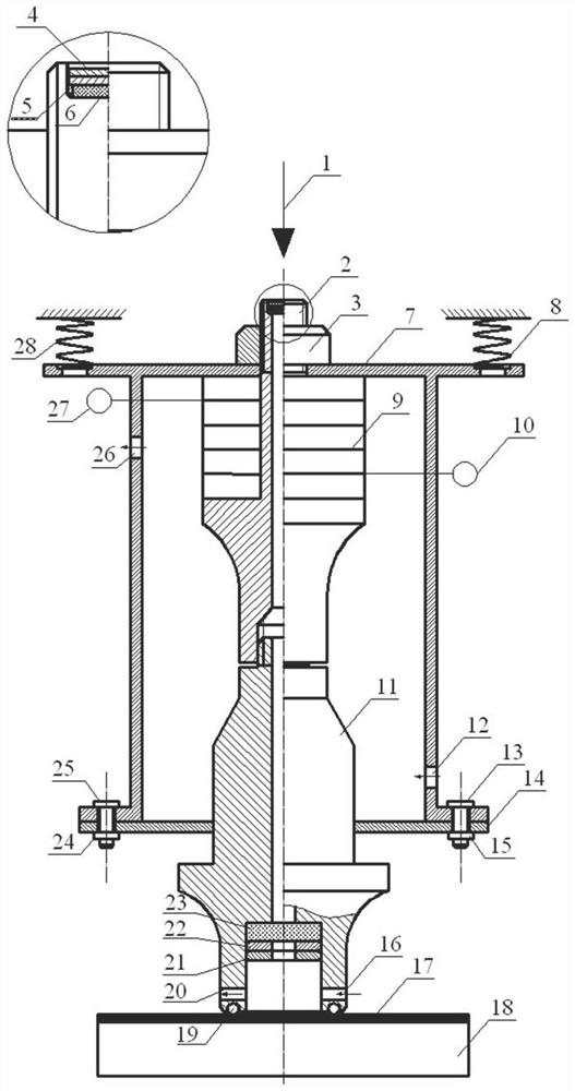
[0024] like figure 1 As shown, the ultrasonic vibration device for coaxial ultrasonic-assisted laser shot peening according to the present invention mainly includes a vibrating rod 2, a horn 11, piezoelectric ceramics 9, a first optical glass 6, and a second optical glass 23 , wherein the light transmittance of the first optical glass 6 and the second optical glass 23 is higher than 99.9%.

[0025] The axial center of the vibrating rod 2 and the horn 11 is processed with a through hole, the lower end of the vibrating rod 2 is fixedly connected with the upper end of the horn 11; the first optical glass 6 is located on the top of the vibrating rod 2, and the second optical glass 23 is located on the horn 11 bottom. Specifically, concave holes are provided on the top of th...


PUM

PropertyMeasurementUnit
thicknessaaaaaaaaaa
transmittivityaaaaaaaaaa

Abstract

The invention provides an ultrasonic vibration device for coaxial ultrasonic-assisted laser shot peening, which mainly includes a vibration rod, a horn, a piezoelectric ceramic, a first optical glass, a second optical glass, a vibration rod and a horn A through hole is machined in the axial center, and the lower end of the vibration rod is fixedly connected with the upper end of the horn; the first optical glass is located on the top of the vibration rod, and the second optical glass is located at the bottom of the horn. The upper end of the vibrating rod extends out of the upper surface of the upper casing and is fixedly connected with it, and the piezoelectric ceramic is mounted on the vibrating rod. In the ultrasonic vibration device, after the piezoelectric ceramic is energized, the electrical energy is converted into mechanical energy to generate ultrasonic waves, and the amplitude of the mechanical vibration is amplified through the horn. A through hole is machined in the axial center of the vibrating rod and the horn, which provides a propagation channel for the laser, and realizes the coaxial propagation of the ultrasonic vibration wave and the laser shock wave. To ensure the coupling of the two during the propagation process, to promote the dynamic recrystallization behavior of the material, and to prepare metal parts with ultra-fine grain surfaces.

Description

technical field [0001] The patent of the invention belongs to the field of ultrasonic-assisted laser processing, and particularly refers to an ultrasonic vibration device for coaxial ultrasonic-assisted laser shot peening. Background technique [0002] Laser shot peening technology uses the interaction between laser and material to generate plasma detonation wave, and the pressure of detonation wave propagates inside the material at extremely high speed and ultra-high pressure, inducing high-density dislocation structure and a certain degree of grain refinement. For example, the invention patent application with the application number CN201810047122.4 proposes a method for refining and strengthening the surface grains of copper-chromium alloys. Through laser shock strengthening technology, fine particles and high residual compressive stress are formed on the surface area of ​​copper-chromium alloys. The fine-grained layer, on the one hand, refines the surface structure of c...

Claims


Application Information

Patent Timeline
Patent Type & Authority Patents(China)
IPC IPC(8): C21D10/00B06B1/06
CPCB06B1/06C21D10/005
Inventor 孟宪凯汪卉周建忠许晓静黄舒李京
Owner JIANGSU UNIV
Why Eureka
Try Eureka