
Vertical cleaning system for stainless steel pipe production

A cleaning system and technology for stainless steel pipes, which are applied in the directions of cleaning hollow objects, cleaning methods and utensils, chemical instruments and methods, etc., can solve the problems of low cleaning efficiency, collision of steel pipes, waste of cleaning costs, etc.

Inactive Publication Date: 2020-09-25
吕钢
View PDF2 Cites 3 Cited by
  • Summary
  • Abstract
  • Description
  • Claims
  • Application Information

AI Technical Summary

Problems solved by technology

[0010] Aiming at the deficiencies of the prior art, the present invention provides a vertical cleaning system for stainless steel pipe production, which solves the problem that most of the existing stainless steel pipe cleaning equipment cleans or High-pressure steam jet cleaning is not thorough, and it is easy to cause steel pipes to collide with each other, resulting in scratches on the surface of the steel pipe after surface treatment. At the same time, the existing vertical stainless steel pipe cleaning equipment is not thorough, and the cleaning efficiency is low. By driving the semi-open-loop scrubbing block to move up and down for cleaning, only the outer surface of one side of the stainless steel pipe can be cleaned, while the other side of the outer surface of the steel pipe and the hole wall of the steel pipe cannot be cleaned well, and at the same time, it can only be cleaned at one time One steel pipe has low cleaning efficiency, which greatly wastes the cleaning cost. It cannot realize the centralized recycling of the cleaned waste liquid, and directly discharges or splashes the cleaning waste water to the outside, which will cause serious waste of water resources.

Method used


Image

  • Vertical cleaning system for stainless steel pipe production
  • Vertical cleaning system for stainless steel pipe production
  • Vertical cleaning system for stainless steel pipe production

Examples


Embodiment Construction

[0043] The following will clearly and completely describe the technical solutions in the embodiments of the present invention with reference to the accompanying drawings in the embodiments of the present invention. Obviously, the described embodiments are only some, not all, embodiments of the present invention. Based on the embodiments of the present invention, all other embodiments obtained by persons of ordinary skill in the art without making creative efforts belong to the protection scope of the present invention.

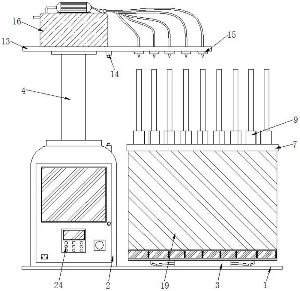
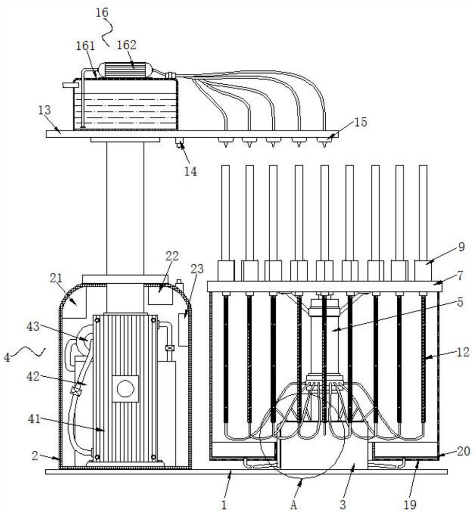
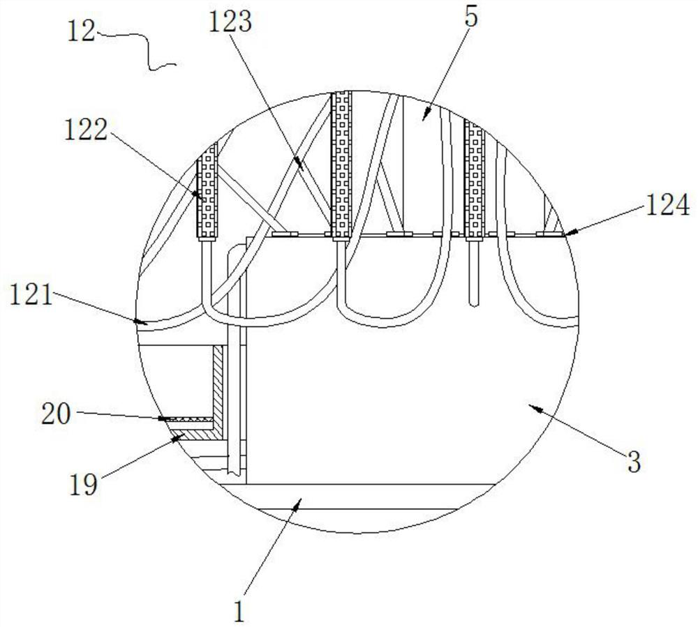
[0044] see Figure 1-12 , the embodiment of the present invention provides a technical solution: a vertical cleaning system for stainless steel pipe production, including a base plate 1 and a hydraulic cabinet 2 and a drive cabinet 3 fixedly installed on the top of the base plate 1 from left to right, and the interior of the hydraulic cabinet 2 The hydraulic assembly 4 is fixedly connected by bolts, and the top of the drive case 3 is fixedly connected with a c...


PUM


Abstract

The invention discloses a vertical cleaning system for stainless steel pipe production. The vertical cleaning system comprises a base plate as well as a hydraulic case and a driving case which are sequentially and fixedly mounted at the top of the base plate from left to right; a hydraulic assembly is fixedly connected inside the hydraulic case through bolts; a protection barrel is fixedly connected at the top of the driving case; and a rotating shaft is rotationally connected inside the protection barrel through a bearing. The invention relates to the technical field of stainless steel pipe production equipment. According to the vertical cleaning system for stainless steel pipe production, every steel pipe can be well cleaned without mutual influence through separate, independent and simultaneous cleaning of the steel pipes and can be cleaned thoroughly, hole walls of the steel pipes are cleaned, defective products are greatly reduced, meanwhile, the multiple steel pipes can be cleaned in all directions at a time, non-stop loading and unloading can be realized in the cleaning process, loading and unloading operations can be performed by just one person, the cleaning efficiency ishigh, and the cleaning cost is greatly saved.

Description

technical field [0001] The invention relates to the technical field of stainless steel pipe production equipment, in particular to a vertical cleaning system for stainless steel pipe production. Background technique [0002] Stainless steel pipe is a kind of hollow long round steel, which is widely used in petroleum, chemical, medical, food, light industry and mechanical instruments and other industrial pipelines and mechanical structural components. In addition, when the bending and torsional strength are the same , light weight, so it is also widely used in the manufacture of mechanical parts and engineering structures, and is also commonly used as furniture and kitchen utensils. Stainless steel pipes need to be cleaned during the production process to remove oil stains, processing dust or other impurities on the surface of stainless steel pipes. [0003] With reference to the cleaning device of a stainless steel pipe with the Chinese patent publication number CN209020800U...

Claims


Application Information

Patent Timeline
Patent Type & Authority Applications(China)
IPC IPC(8): B08B9/023B08B9/027
CPCB08B9/023B08B9/027
Inventor 吕钢
Owner 吕钢
Learn More