
Mineral wool fiber centrifugal fiber forming device and process

A technology of mineral wool fiber and centrifugal fiber formation, which is applied in the direction of manufacturing tools and glass manufacturing equipment, and can solve the problems of large randomness, uncontrollable fiber thickness, and failure to meet production needs.

Inactive Publication Date: 2020-09-22
浙江浦森新材料科技有限公司
View PDF0 Cites 3 Cited by
  • Summary
  • Abstract
  • Description
  • Claims
  • Application Information

AI Technical Summary

Problems solved by technology

[0003] In the mineral wool production process, the mineral wool fiber forming system is the key process of mineral wool fiber forming. The fiber forming system determines the fiber production, fiber diameter, slag ball content, and the uniformity of fiber spray glue in mineral wool production. However, there are still various deficiencies in the mineral wool fiber centrifugal fiber forming device and its technology that appear on the market, and cannot meet the needs of production.
[0004] During the operation of the existing mineral wool fiber centrifugal fiber forming device and its process, most of the mineral wool fiber melt liquid is attached to the centrifugal roller, and the melt liquid is subjected to the centrifugal force of the centrifugal roller to form chemical fibers, which has a large randomness. As a result, the thickness of the fiber filament after chemical fiber is uncontrollable, and the melt liquid is easily affected by the slag ball during the centrifugation process. Therefore, we propose a mineral wool fiber centrifugal fiber forming device and its process

Method used


Image

  • Mineral wool fiber centrifugal fiber forming device and process
  • Mineral wool fiber centrifugal fiber forming device and process
  • Mineral wool fiber centrifugal fiber forming device and process

Examples


Embodiment Construction

[0034] The following will clearly and completely describe the technical solutions in the embodiments of the present invention with reference to the accompanying drawings in the embodiments of the present invention. Obviously, the described embodiments are only some, not all, embodiments of the present invention. Based on the embodiments of the present invention, all other embodiments obtained by persons of ordinary skill in the art without making creative efforts belong to the protection scope of the present invention.

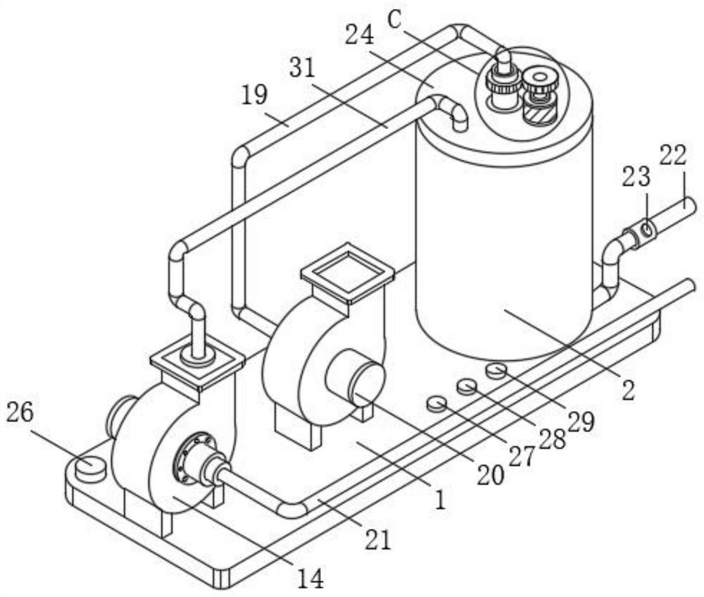
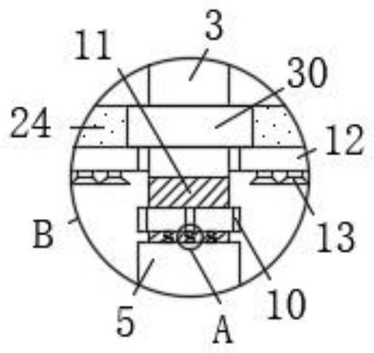
[0035] see Figure 1-8, the present invention provides a mineral wool fiber centrifugal fiber forming device and its technical scheme: a mineral wool fiber centrifugal fiber forming device, comprising a base 1, a centrifuge cylinder 2 is arranged on the top of the base 1, and the inside of the centrifuge cylinder 2 is A centrifugal roller 3 is provided, the surface of the centrifugal roller 3 is sleeved with a first bearing 30, and the first bearing 30 is clam...


PUM


Abstract

The invention discloses a mineral wool fiber centrifugal fiber forming device. The mineral wool fiber centrifugal fiber forming device comprises a base, a centrifugal cylinder is arranged at the top of the base, a centrifugal roller is arranged in the centrifugal cylinder, the surface of the centrifugal roller is sleeved with a first bearing, the first bearing is connected to the bottom of a cylinder cover in a clamped mode, the bottom of the cylinder cover is arranged at the top of the centrifugal cylinder, and first centrifugal spray holes are formed in the surface of the centrifugal roller.The centrifugal roller, a centrifugal sleeve, the first centrifugal spray holes, second centrifugal spray holes, a nut, an external thread, an elastic device, a wheel disc, a wheel disc groove and afilter screen are designed to be matched with one another; the problems of an existing mineral wool fiber centrifugal fiber forming device and the problems in the operation of process that mineral wool fiber melt liquid is always attached to a centrifugal roller, the melt liquid is subjected to chemical fibers under the action of centrifugal force of the centrifugal roller, randomness is large, the thickness of fiber filaments obtained after chemical fibers are made to be uncontrollable, and the melt liquid is prone to being affected by slag balls in the centrifugal process are solved.

Description

technical field [0001] The invention belongs to the technical field of mineral wool production, and in particular relates to a mineral wool fiber centrifugal fiber forming device and a process thereof. Background technique [0002] Mineral wool and its products are light, durable, non-combustible, non-rotten, and free from moths, etc. They are excellent heat insulation and sound-absorbing materials. Cotton-like short fibers made from silicate melts, including slag wool, mineral wool, glass wool and ceramic fibers, etc., generally only refer to the first two in my country. The earliest mineral wool obtained from the Hawaiian crater was called "Fall's hair". Those whose main raw materials are metallurgical slag or fly ash are called slag wool; those whose main raw materials are rocks such as basalt are called "mineral wool". Crushing the raw materials into a certain particle size, adding additives, etc. for batching, and then melting in the furnace, forming cotton, and packi...

Claims


Application Information

Patent Timeline
Patent Type & Authority Applications(China)
IPC IPC(8): C03B37/04
CPCC03B37/04
Inventor 夏扬
Owner 浙江浦森新材料科技有限公司
Learn More