
High-frequency high-voltage coil framework

A coil bobbin, high frequency and high voltage technology, applied in the direction of transformer/inductor coil/winding/connection, transformer/inductor shell, transformer/inductor components, etc., can solve the problems affecting power miniaturization, compact structure design, Voltage and current waveform distortion, increasing switching loss, etc., to solve the problem of coil insulation isolation, reduce distributed capacitance, and reduce volume

Pending Publication Date: 2020-09-15
胡伟
View PDF0 Cites 0 Cited by
  • Summary
  • Abstract
  • Description
  • Claims
  • Application Information

AI Technical Summary

Problems solved by technology

[0003] As the operating voltage of high-frequency high-voltage transformers continues to increase, the step-up ratio of the transformer is required to increase continuously, and the turn ratio of the secondary winding of the transformer is also increasing. The high turn ratio and high voltage make insulation difficult to deal with, leakage inductance and distributed capacitance, etc. Parasitic parameters cause surge voltage and surge current to the pre-stage power switch tube, distort the voltage and current waveform, and increase switching loss. The substantial increase in the volume of the power supply affects the miniaturization and compact structure design of the power supply. In view of these situations, in order to avoid the above-mentioned technical problems, it is necessary to provide a high-frequency and high-voltage coil bobbin to overcome the above-mentioned defects in the prior art

Method used


Image

  • High-frequency high-voltage coil framework
  • High-frequency high-voltage coil framework
  • High-frequency high-voltage coil framework

Examples


Embodiment Construction

[0015] The following will clearly and completely describe the technical solutions in the embodiments of the present invention with reference to the accompanying drawings in the embodiments of the present invention. Obviously, the described embodiments are only some, not all, embodiments of the present invention. Based on the embodiments of the present invention, all other embodiments obtained by persons of ordinary skill in the art without making creative efforts belong to the protection scope of the present invention.

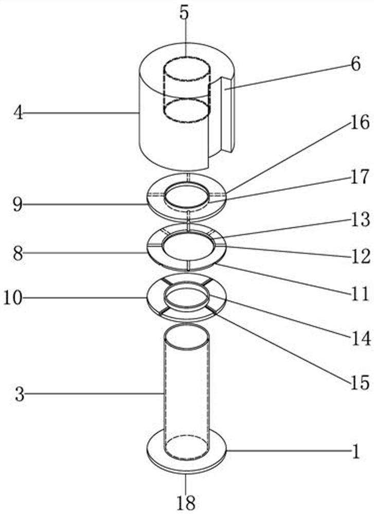
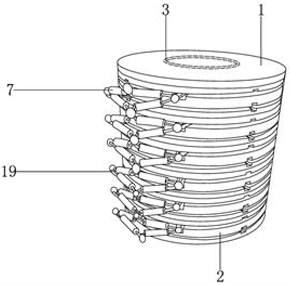
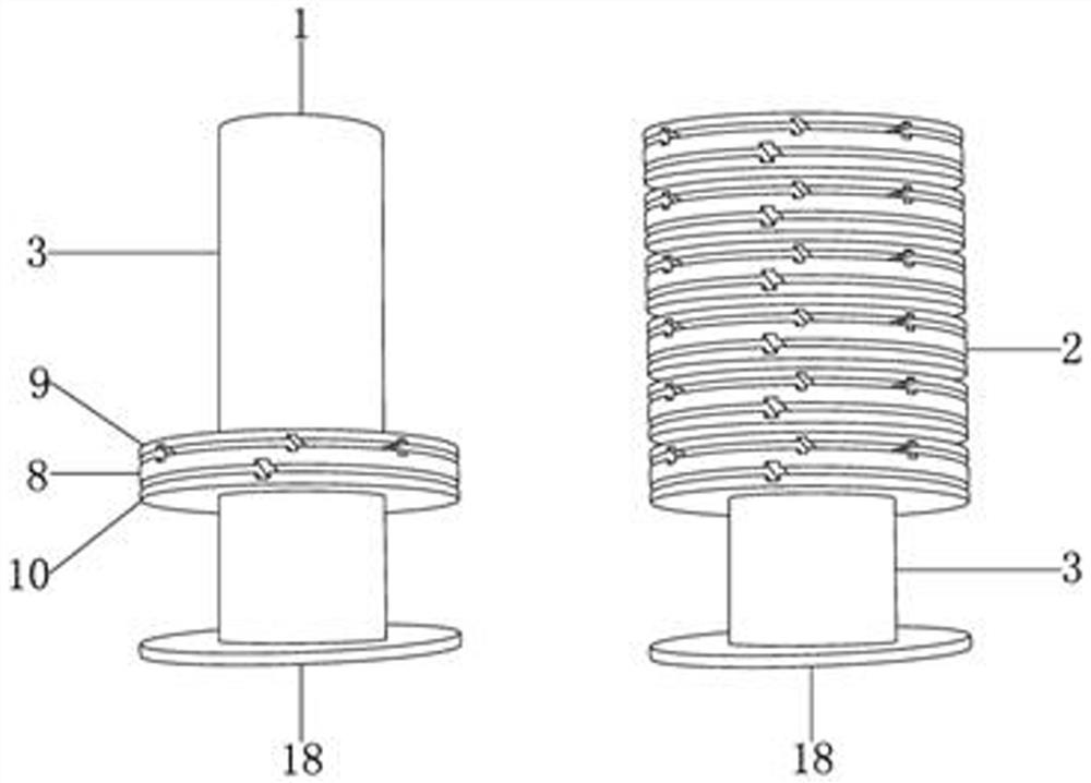
[0016] see Figure 1-3 , the present invention provides a technical solution: a high-frequency and high-voltage coil skeleton, including a sleeve rod 1, a wire frame 2 is sleeved on the outside of the sleeve rod 1, and there are at least six wire frames 2, and the inside of the wire frame 2 is provided with Oil wire 19, and the oil wire 19 is clamped and connected with the wire frame 2, and the lead of the oil wire 19 is provided with a diode 7, and the diode ...


PUM


Abstract

The invention discloses a high-frequency high-voltage coil framework which comprises a sleeve rod, a plurality of coil holders are arranged outside the sleeve rod in a sleeving mode, oil lines are arranged in the coil holders, the oil lines are connected with the coil holders in a clamped mode, and the annular coil holders are formed by processing PPO materials. A plurality of diodes are arrangedon leads at the oil lines, are in tin soldering connection with the leads at the oil lines, and are connected in series through the leads at the oil lines. The high-frequency high-voltage coil framework is formed by combining a plurality of annular coil holders, the high power high voltage output is achieved, a plurality of annular coil holders are primarily connected in parallel by using diodes and oil lines to serve as input; the secondary output of each coil holder is rectified and filtered and then is output in series from bottom to top; the size of an element is greatly reduced, the sizeof the transformer is reduced, the shell is formed by processing PBT materials, the insulation strength and the mechanical strength thereof are improved through grooves, meanwhile, the size of the transformer is reduced, the insulation isolation problem of a high-frequency boosting transformer coil is solved, and the transformer is suitable for application and popularization.

Description

technical field [0001] The invention relates to the technical field of transformer coil bobbins, in particular to a high-frequency and high-voltage coil bobbin. Background technique [0002] The high-frequency high-voltage transformer occupies an important position in the high-frequency high-voltage power supply system. It is a key component of the entire system. The effect of pressure; [0003] As the operating voltage of high-frequency high-voltage transformers continues to increase, the step-up ratio of the transformer is required to increase continuously, and the turn ratio of the secondary winding of the transformer is also increasing. The high turn ratio and high voltage make insulation difficult to deal with, leakage inductance and distributed capacitance, etc. Parasitic parameters cause surge voltage and surge current to the pre-stage power switch tube, distort the voltage and current waveform, and increase switching loss. The substantial increase in the volume of ...

Claims


Application Information

Patent Timeline
IPC IPC(8): H01F27/32H01F27/40H01F27/28H01F27/02
CPCH01F27/02H01F27/2823H01F27/2828H01F27/324H01F27/325H01F27/40H01F2027/408
Inventor 胡伟
Owner 胡伟
Learn More