Multi-mode switching circuit and voltage stabilizer

A switching circuit, multi-mode technology, used in instruments, regulating electrical variables, control/regulating systems, etc., can solve problems such as small static current, low supply voltage, voltage overshoot, etc., to avoid voltage overshoot and achieve smooth switching. Effect

Active Publication Date: 2020-09-15
AUTOCHIPS WUHAN CO LTD
View PDF5 Cites 0 Cited by
  • Summary
  • Abstract
  • Description
  • Claims
  • Application Information

AI Technical Summary

Problems solved by technology

In standby mode, most components of the chip are in a closed or fixed logic state, only a small number of circuits work at a lower frequency, and a lower power supply voltage can also meet the working requirements. The entire chip current is mainly low-frequency low-voltage circuit power consumption and leakage. At this time, the LDO is required to provide a lower supply voltage and a small quiescent current, and the bandwidth of the LDO is not high, but the voltage overshoot will be caused by the sudden change of the load when the mode is switched.
Therefore, it is a very big challenge to design an LDO that meets the requirements of both working mode and standby mode, suppresses the overshoot generated during mode switching, and has high bandwidth and ultra-low power consumption.

Method used


Image

  • Multi-mode switching circuit and voltage stabilizer
  • Multi-mode switching circuit and voltage stabilizer
  • Multi-mode switching circuit and voltage stabilizer

Examples


Embodiment Construction

[0019] The following will clearly and completely describe the technical solutions in the embodiments of the application with reference to the accompanying drawings in the embodiments of the application. Apparently, the described embodiments are only part of the embodiments of the application, not all of them. Based on the implementation manners in this application, all other implementation manners obtained by persons of ordinary skill in the art without making creative efforts belong to the scope of protection of this application.

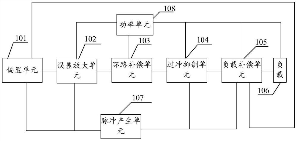
[0020] See figure 1 , is a schematic block diagram of the multi-mode switching circuit of the present invention. The multi-mode switching circuit includes: a bias unit 101 for providing a reference voltage VERF, an error amplification unit 102 connected with the bias unit 101 and the pulse generation unit 107, and receiving from the bias unit 101 The reference voltage VERF receives a second control signal from the pulse generation unit 107; the lo...


PUM


Abstract

The invention provides a multi-mode switching circuit and a voltage stabilizer, and the circuit comprises a pulse generation unit which is used for receiving a first control signal and generating a second control signal and a pulse signal according to the first control signal; a bias unit which is connected with the pulse generation unit and is used for receiving the first control signal and the input voltage and outputting a reference voltage, a first bias voltage and a second bias voltage; an error amplification unit which is connected with the bias unit and the pulse generation unit, and isused for receiving the reference voltage, the first bias voltage and the second bias voltage from the bias unit, receiving the second control signal from the pulse generation unit and then providingan output voltage; a load compensation unit which is connected with the pulse generation unit and the bias unit and used for receiving the second control signal from the pulse generation unit, receiving the first bias voltage and the second bias voltage from the bias unit and providing the minimum load; and a power unit which is connected with the error amplification unit and the load compensationunit and used for providing output voltage. Therefore, overshoot during mode switching is prevented.

Description

technical field [0001] The present application relates to the technical field of voltage regulators, in particular to a multi-mode switching circuit and a voltage regulator. Background technique [0002] Low dropout regulator (LDO) is widely used in System-on-Chip (SoC) and Micro-controller Unit (MCU) to provide stable power to digital or analog circuits. In low-power applications, chips generally have multiple modes, typically at least working mode and standby mode. In the working mode, the chip generally has to process a large amount of data. The digital circuit has a high operating frequency and requires a high supply voltage. At the same time, the current consumed is very large and changes rapidly. At this time, the LDO needs to provide a large supply voltage and high bandwidth. . In standby mode, most components of the chip are in a closed or fixed logic state, only a small number of circuits work at a lower frequency, and a lower power supply voltage can also meet th...

Claims


Application Information

Patent Timeline
Patent Type & Authority Applications(China)
IPC IPC(8): G05F1/56
CPCG05F1/561
Inventor 陈盈吉王科
Owner AUTOCHIPS WUHAN CO LTD
Why Eureka
Try Eureka