Ophthalmic optical coherence tomography scanner and eye scanning image acquisition method
An optical coherence tomography and image scanning technology, which is applied in the field of medical devices, can solve problems such as eye immobility, long manual adjustment time, and differences in image clarity, and achieve the effects of expanding application scenarios and improving efficiency and accuracy
- Summary
- Abstract
- Description
- Claims
- Application Information
AI Technical Summary
Problems solved by technology
Method used
Image
Examples
Embodiment 1
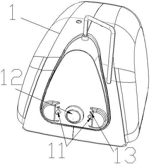
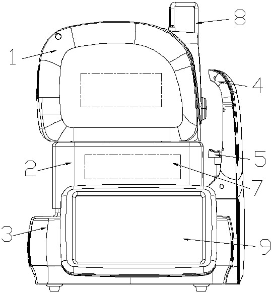
[0046] Example 1: Reference figure 1 , image 3 with Figure 4 , An optical coherence tomography scanner for ophthalmology, comprising a base 3, a driving mechanism 7 and an optical head assembly 1 arranged in order from bottom to top. The driving mechanism 7 includes three motors, so that the optical head assembly 1 arranged on the driving mechanism 7 can move up and down, forward and backward, and left and right. The optical head assembly 1 is equipped with an iris camera group 11, which is used for shooting. The eye surface of the tested object and the image including the optical head assembly 1; a controller 34 is installed in the base 3, and the controller 34 calculates the distance that the optical head assembly 1 needs to move based on the images taken by the iris camera group 11, and then The driving mechanism 7 is controlled so that the driving mechanism 7 drives the optical head assembly 1 to move to a corresponding position. The iris camera group 11 and the controlle...
Embodiment 2
[0048] Example 2, reference figure 1 with figure 2 , An ophthalmic optical coherence tomography scanner, further comprising a forehead rest and jaw rest assembly vertically arranged on one side of the base 3, the forehead rest and jaw rest assembly includes a forehead rest 4 and a jaw rest 5, the chin of the tested person is placed on the jaw On the support 5, the forehead is in contact with the forehead support 4, thus positioning the head of the tested person. The forehead support and jaw support assembly also includes a drive motor, which is used to drive the forehead support and jaw support assembly to move. The forehead support and jaw support assembly has an independent motion control structure to control the movement of the drive motor. The function is to work with the drive mechanism 7 to automatically adjust the measured The eyes of the person demand the relative position with the optical head assembly 1. The optical head assembly 1 includes a housing and an eyepiece ...
Embodiment 3
[0058] Example 3, reference Image 6 , An eye scan image acquisition method of an ophthalmic optical coherence tomography scanner, comprising the following steps:
[0059] 1. Turn on the device, connect the device to an external power supply, and supply power to all electrical components so that all electrical components can work. The electrical components include: scanner 31, voice player 32, controller 34, drive mechanism 7. Optical Head assembly 1;
[0060] 2. The code scanner 31 reads the information of the person under test, and the person under test aligns the barcode or QR code with the scanning port of the code scanner 31. After the code scanner 31 reads the scanned information, the information is entered into the controller 34 ;
[0061] 3. Turn on the voice player 32, the controller 34 controls the voice player 32 to play the voice, and the voice includes prompting the tested person to place the head on the forehead rest and jaw rest component;
[0062] 4. The iris camera g...
PUM
 Abstract
Description
Claims
Application Information
 - R&D
- Intellectual Property
- Life Sciences
- Materials
- Tech Scout
- Unparalleled Data Quality
- Higher Quality Content
- 60% Fewer Hallucinations
Browse by: Latest US Patents, China's latest patents, Technical Efficacy Thesaurus, Application Domain, Technology Topic, Popular Technical Reports.
© 2025 PatSnap. All rights reserved.Legal|Privacy policy|Modern Slavery Act Transparency Statement|Sitemap|About US| Contact US: help@patsnap.com


