


Quick Research
Generate reliable direction feasibility study reports for your R&D in just a few steps.

Technical Q&A
Discover and master advanced knowledge NOW. Basics, ideas, possibilities, all at once.

Find Solutions
As an expert in R&D theories, this can generate solutions to your technical problems instantly.

Evaluate Feasibility
Analyze your overall solution with one click, know your potential R&D risks in advance.

Monitor Landscape
Get weekly tech updates, stay abreast of the latest tech innovations and key insights.
A 3D structured light 940nm narrow-band filter and its preparation method
A technology of narrow-band optical filter and structured light, which is applied in the field of optical filter to achieve the effect of accurate wavelength positioning and good steepness
- Summary
- Abstract
- Description
- Claims
- Application Information
AI Technical Summary
Problems solved by technology
Method used
Image

Examples
Embodiment 1
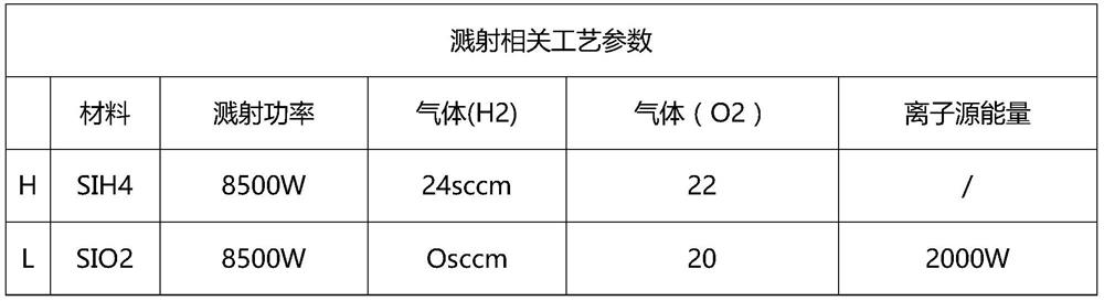
[0017] see figure 1 , in an embodiment of the present invention, a 3D structured light 940nm narrow-band filter includes a substrate, one side of the substrate is alternately evaporated with silicon dioxide layers and silicon tetrahydrogen layers, and the other side of the substrate is alternately evaporated with silicon dioxide Silicon layer and silicon tetrahydrogen layer, the total number of layers of the silicon dioxide layer and silicon tetrahydrogen layer on each side is set to 20-40 layers, the refractive index of the silicon tetrahydrogen is 4.41, and the silicon dioxide The refractive index is 1.48; the sputtering parameters of the silicon tetrahydrogen are: sputtering power 8500W, H 2 24sccm, O 2 It is 22sccm; the sputtering parameters of silicon dioxide are: sputtering power 8500W, H 2 0sccm, O 2 It is 20sccm, and the ion source energy is 2000w.
[0018] Preferably, the thickness of the silicon dioxide layer on each side is set to 1300-2000 nm, and the thickness...
Embodiment 2
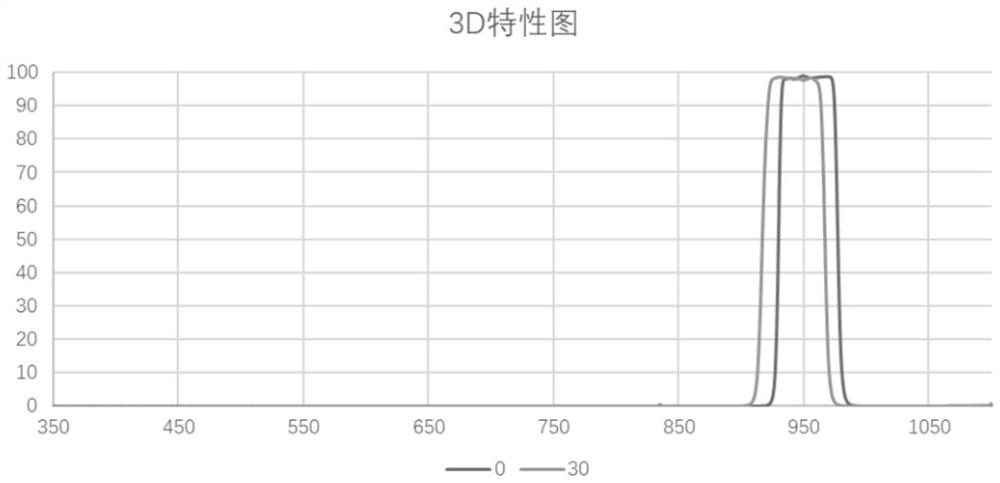
[0036] see figure 1 with figure 2 , in an embodiment of the present invention, a 3D structured light 940nm narrow-band filter includes a substrate, one side of the substrate is alternately evaporated with silicon dioxide layers and silicon tetrahydrogen layers, and the other side of the substrate is alternately evaporated with silicon dioxide For the silicon layer and the silicon tetrahydrogen layer, the total number of layers of the silicon dioxide layer and the silicon tetrahydrogen layer on each side is set to 27 layers.
[0037] Preferably, the thickness of the outermost silicon dioxide layer on each side is set to 100 nm, and 100 nm is the outermost layer in order to prevent the silicon tetrahydrogen layer from reacting with components in the air.
[0038] Preferably, the substrate is set to be AF32 glass or D263T glass.
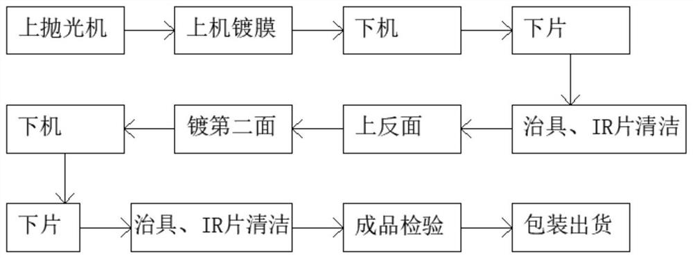
[0039] A preparation method of a 3D structured light 940nm narrow-band filter, comprising the following steps:
[0040] Step 1: Select the substrat...
PUM
| Property | Measurement | Unit |
|---|---|---|
| thickness | aaaaa | aaaaa |
| thickness | aaaaa | aaaaa |
| thickness | aaaaa | aaaaa |
Abstract
Description
Claims
Application Information
 - R&D Engineer
- R&D Manager
- IP Professional
- Industry Leading Data Capabilities
- Powerful AI technology
- Patent DNA Extraction
Browse by: Latest US Patents, China's latest patents, Technical Efficacy Thesaurus, Application Domain, Technology Topic, Popular Technical Reports.
© 2024 PatSnap. All rights reserved.Legal|Privacy policy|Modern Slavery Act Transparency Statement|Sitemap|About US| Contact US: help@patsnap.com