
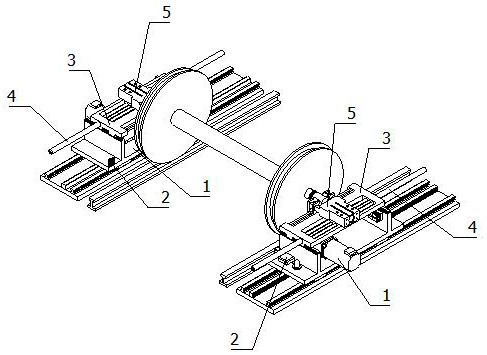
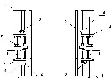
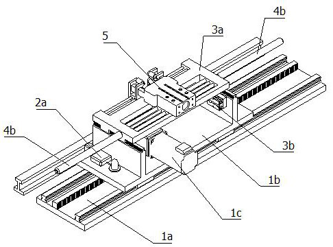
High-precision wheel set positioning and transferring mechanism for production of railway vehicles

A railway vehicle, high-precision technology, applied in conveyors, conveyor objects, mechanical conveyors, etc., can solve the problems of no protection mechanism, rack damage, danger, etc., and achieve the effect of reducing accuracy requirements

Inactive Publication Date: 2020-09-08
殷建平
View PDF1 Cites 2 Cited by
  • Summary
  • Abstract
  • Description
  • Claims
  • Application Information

AI Technical Summary

Problems solved by technology

[0005] 1. Two sets of sliding bases that work synchronously are used. Once one set fails and stops immediately, the other set will continue to move forward, which will cause the wheelset to fly out of the positioning horizontal moving seat, which is very dangerous;
[0006] 2. If the positioning wheel is too far away, the wheel set can roll for a long distance on the positioning horizontal moving seat. When the positioning horizontal moving seat stops moving, the wheel set will continue to roll under the action of inertia, and then hit the positioning wheel. The rack is damaged and the service life is low;
[0007] 3. There is no corresponding protection mechanism for the problem that the wheelset may be deflected and derailed during the process of sliding on the track

Method used


Image

  • High-precision wheel set positioning and transferring mechanism for production of railway vehicles
  • High-precision wheel set positioning and transferring mechanism for production of railway vehicles
  • High-precision wheel set positioning and transferring mechanism for production of railway vehicles

Examples


Embodiment Construction

[0046] Several embodiments of the present invention will be disclosed in the following drawings. For clear description, many practical details will be described in the following description. However, it should be understood that these practical details should not be used to limit the present invention. In other words, in some embodiments of the present invention, these practical details are unnecessary. In addition, in order to simplify the drawings, some conventionally used structures and components will be shown in simple schematic ways in the drawings.

[0047] In addition, the descriptions related to "first", "second", etc. in the present invention are only used for descriptive purposes, and do not specifically refer to the order or sequence, nor are they used to limit the present invention. They are only used to distinguish between The same technical terms describe only the components or operations, but cannot be understood as indicating or implying their relative importanc...


PUM


Abstract

The invention relates to the technical field of railway production equipment, in particular to a high-precision wheel set positioning and transferring mechanism for production of railway vehicles. Thehigh-precision wheel set positioning and transferring mechanism comprises linear moving devices, synchronous devices and wheel set positioning devices. Each wheel set positioning device comprises a moving mechanism, a buffering mechanism and a shaft positioning mechanism. A wheel set is placed on rails. The shaft positioning mechanisms are arranged on the two sides of the wheel set and clamped ona rotating shaft of the wheel set. The buffering mechanisms are installed below the shaft positioning mechanisms. The working direction of the buffering mechanisms is the same as the conveying direction of the wheel set. The moving mechanisms are installed below the buffering mechanisms and drive the buffering mechanisms to move towards the wheel set from the two sides of the wheel set. The synchronous mechanisms and the moving mechanisms are all installed on the linear moving devices. The linear moving devices are arranged on the two sides of the rails. The conveying direction of the linearmoving devices is the same as the conveying direction of the wheel set. The high-precision wheel set positioning and transferring mechanism does not need high-precision racks, the safety synchronous mechanisms are installed on the linear moving devices of the high-precision wheel set positioning and transferring mechanism, and the wheel set is not prone to running off the rails or neither damagingracks when being conveyed.

Description

Technical field [0001] The invention relates to the technical field of railway production equipment, in particular to a high-precision wheelset positioning and transfer mechanism for railway vehicle production. Background technique [0002] The safety of railway transportation is related to the major issues of national economy and people's livelihood, and the railway wheelset is directly related to the safety of railway transportation. In the process of railway vehicle production and maintenance, there are many working procedures in railway wheel sets, and its professional equipment is diverse. How to effectively and effectively position the wheel sets is related to the quality of the various operations performed on the wheel sets, especially in the wheel sets. How to accurately, safely and smoothly move to the next operation process on the production and assembly line of its related accessories has become a problem that many enterprises that provide non-standard equipment for ra...

Claims


Application Information

Patent Timeline
Patent Type & Authority Applications(China)
IPC IPC(8): B65G35/00B65G47/24B65G43/02G08B21/18G08B21/24
CPCB65G43/02B65G35/00B65G47/24B65G2201/0273
Inventor 殷建平
Owner 殷建平
Learn More