A method and device for self-adapting flow rate adjustment of liquid-cooled cold plate of electronic equipment

An adaptive adjustment, liquid-cooled cold plate technology, applied in the construction of electrical equipment components, modification with liquid cooling, electrical components, etc., can solve the problems of branch flow distribution fluctuations, heat transfer deterioration, etc., to achieve increased cooling Effects of flow rate, improved stability and safety, enhanced cooling capacity

Active Publication Date: 2022-08-05
CHINA ELECTRONICS TECH GRP CORP NO 14 RES INST
View PDF0 Cites 0 Cited by
  • Summary
  • Abstract
  • Description
  • Claims
  • Application Information

AI Technical Summary

Problems solved by technology

[0006] Aiming at the problems existing in the prior art, the object of the present invention is to provide a method and device for self-adaptive adjustment of the flow rate of the liquid-cooled cold plate of electronic equipment, which realizes the self-adaptive adjustment of the flow rate of the cold plate with the temperature through the thermal expansion component, and satisfies the requirements of large-scale liquid cooling systems. In the cooling system, the demand for dynamic adjustment of the flow when the heat load of the local branch changes, especially in the phase change cooling system, solves the problem of heat transfer deterioration caused by the fluctuation of the flow distribution of the branch, ensures effective cooling of the electronic equipment in each branch, and improves Cooling system stability and safety

Method used


Image

  • A method and device for self-adapting flow rate adjustment of liquid-cooled cold plate of electronic equipment
  • A method and device for self-adapting flow rate adjustment of liquid-cooled cold plate of electronic equipment
  • A method and device for self-adapting flow rate adjustment of liquid-cooled cold plate of electronic equipment

Examples


Embodiment Construction

[0020] The technical solutions in the embodiments of the present invention will be clearly and completely described below with reference to the accompanying drawings in the embodiments of the present invention. Obviously, the described embodiments are only a part of the embodiments of the present invention, but not all of the embodiments. Based on the embodiments of the present invention, all other embodiments obtained by those of ordinary skill in the art without creative efforts shall fall within the protection scope of the present invention.

[0021] In the description of the present invention, it should be noted that the orientations or positional relationships indicated by the terms "upper", "lower", "inner", "outer", "top / bottom", etc. are based on the orientations shown in the accompanying drawings Or the positional relationship is only for the convenience of describing the present invention and simplifying the description, rather than indicating or implying that the ref...


PUM


Abstract

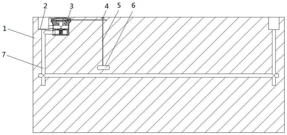
The invention discloses a flow self-adaptive adjustment device for a liquid-cooled cold plate of electronic equipment, which relates to the technical field of electronic equipment cooling, and specifically includes a liquid-cooled cold plate, a thermal expansion part and a flow channel. The top of the flow channel is provided with a liquid inlet on the upper surface of the liquid-cooled cold plate, the inner bottom of the liquid inlet is provided with a throttling part, the thermal expansion part is installed in the liquid-cooled cold plate, and the middle of the side of the liquid inlet passes through the second The bypass branch communicates with the thermal expansion component, the side of the flow channel communicates with the thermal expansion component through the first bypass branch, and a temperature sensing chamber is provided inside the liquid cooling plate, and the temperature sensing chamber communicates with the thermal expansion component through the channel. When applied in large-scale liquid cooling systems, there is no need to add additional components such as electric regulating valves and temperature sensors, and only thermal expansion components are added to the existing conventional cold plate structure, so that the cross-sectional area of ​​the flow channel of the liquid-cooled cold plate can vary with the temperature of the electronic device. Adaptive changes to improve the stability and safety of phase change cooling systems.

Description

technical field [0001] The invention relates to the technical field of electronic equipment cooling, in particular to a flow adaptive adjustment method and device for a liquid-cooled cold plate of electronic equipment. Background technique [0002] With the development of electronic technology and the continuous improvement of application requirements, the integration and power density of electronic devices have increased significantly. In many applications, the heat dissipation capacity of electronic devices has become one of the bottlenecks restricting their performance. At present, the more common cooling method is mainly forced air cooling, because of its low heat dissipation efficiency, it is difficult to meet the increasingly stringent heat dissipation requirements of electronic equipment. Liquid cooling technology, especially phase change cooling technology, has been rapidly developed and applied in recent years due to its advantages of high heat dissipation efficienc...

Claims


Application Information

Patent Timeline
Patent Type & Authority Patents(China)
IPC IPC(8): H05K7/20
CPCH05K7/2029H05K7/20327H05K7/20381
Inventor 吴进凯钱吉裕李力陈琦
Owner CHINA ELECTRONICS TECH GRP CORP NO 14 RES INST
Why Eureka
Try Eureka