
Device testing structure and its manufacturing method and testing method

A technology for testing structures and manufacturing methods, applied in semiconductor/solid-state device testing/measurement, single semiconductor device testing, semiconductor/solid-state device manufacturing, etc., to solve problems such as inability to form shadow effects and leakage currents that cannot be measured

Active Publication Date: 2022-08-09
SHANGHAI HUAHONG GRACE SEMICON MFG CORP
View PDF11 Cites 0 Cited by
  • Summary
  • Abstract
  • Description
  • Claims
  • Application Information

AI Technical Summary

Problems solved by technology

[0006] The purpose of the present invention is to provide a device test structure and its manufacturing method and test method, to at least solve the problem that the existing device test structure cannot form shadow effects, so that the leakage current caused by shadow effects cannot be measured

Method used


Image

  • Device testing structure and its manufacturing method and testing method
  • Device testing structure and its manufacturing method and testing method
  • Device testing structure and its manufacturing method and testing method

Examples


Embodiment Construction

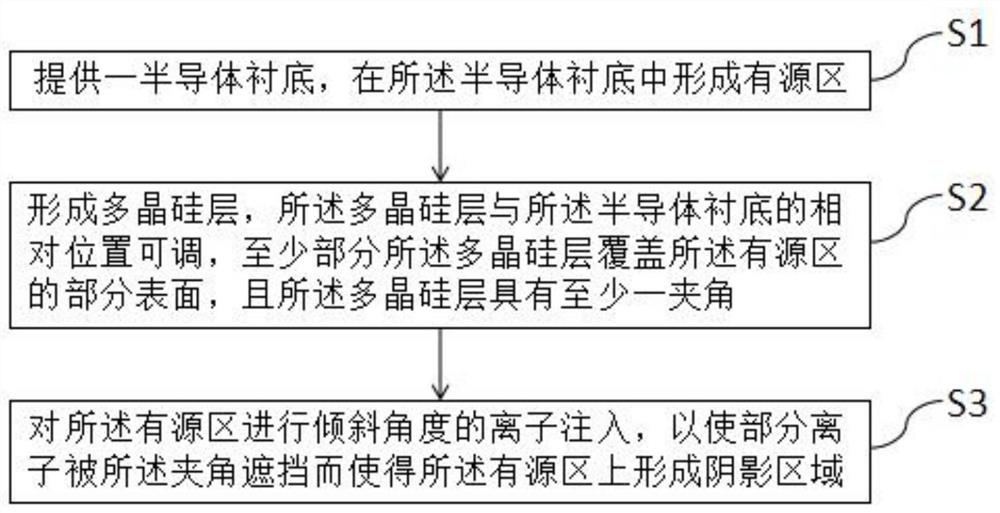
[0031] The device testing structure and its manufacturing method and testing method proposed by the present invention will be further described in detail below with reference to the accompanying drawings and specific embodiments. It should be noted that the accompanying drawings are all in a very simplified form and in inaccurate scales, and are only used to facilitate and clearly assist the purpose of explaining the embodiments of the present invention. Furthermore, the structures shown in the drawings are often part of the actual structure. In particular, each drawing needs to show different emphases, and sometimes different scales are used.

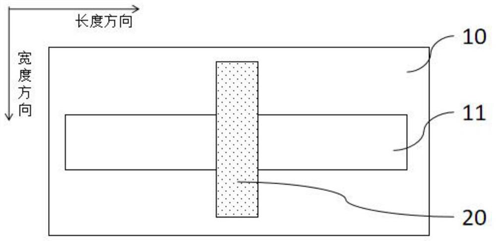
[0032] In the prior art, device test structures such as figure 1 As shown, an active region 11 is formed in a semiconductor substrate 10, and a polysilicon layer 20 is formed on the substrate 10. At least part of the polysilicon layer 20 covers part of the surface of the active region 11, and the polysilicon Layer 20 is inline. Beca...


PUM


Abstract

The present invention provides a device testing structure, a manufacturing method and a testing method thereof. In the device testing structure, the polysilicon layer on the semiconductor substrate has at least one included angle, and when the active region in the semiconductor substrate is measured When performing ion implantation at an oblique angle, some ions form a shadow area on the active due to the occlusion of the included angle. A shadow area can be formed, so the leakage current caused by the shadow effect can be measured. Thus, after adjusting the size of the shadow area relative to the active area to obtain the leakage current as a function of the size of the shadow area , the size of the leakage current caused by the shadow region on the active region of the target wafer can be accurately obtained according to the size of the shadow region on the active region of the target wafer.

Description

technical field [0001] The present invention relates to the technical field of semiconductors, in particular to a device testing structure and a manufacturing method and testing method thereof. Background technique [0002] With the continuous expansion of different application scenarios of chips, more and more stringent requirements are placed on the power consumption of chips. The source of chip power consumption mainly comes from the leakage of the device itself on the chip and the leakage caused by the chip design. [0003] In the prior art, in order to reduce the punch through of the device caused by the short channel effect, the ion implantation at an oblique angle is usually used in the ion implantation (pocket IMP) in the lightly doped drain region. Although this slanted ion implantation can effectively reduce the punch-through caused by the short channel effect, it may also cause leakage due to the shadowing effect, which is caused by the slanted ion implantation i...

Claims


Application Information

Patent Timeline
Patent Type & Authority Patents(China)
IPC IPC(8): H01L21/265H01L21/66G01R31/26
CPCH01L21/265H01L22/14H01L22/20H01L22/34G01R31/2601G01R31/2644
Inventor 孙访策张明黄冲
Owner SHANGHAI HUAHONG GRACE SEMICON MFG CORP
Learn More