


Quick Research
Generate reliable direction feasibility study reports for your R&D in just a few steps.

Technical Q&A
Discover and master advanced knowledge NOW. Basics, ideas, possibilities, all at once.

Find Solutions
As an expert in R&D theories, this can generate solutions to your technical problems instantly.

Evaluate Feasibility
Analyze your overall solution with one click, know your potential R&D risks in advance.

Monitor Landscape
Get weekly tech updates, stay abreast of the latest tech innovations and key insights.
A hot dirty gas self-control valve for industrial environmental protection equipment
A technology for environmental protection equipment and automatic control valves, which is applied in mechanical equipment, valve devices, valve details, etc., and can solve problems such as large resistance on the inner wall of the valve body, damage to the valve core, and affecting the flow of air.
- Summary
- Abstract
- Description
- Claims
- Application Information
AI Technical Summary
Problems solved by technology
Method used
Image

Examples
Embodiment 1
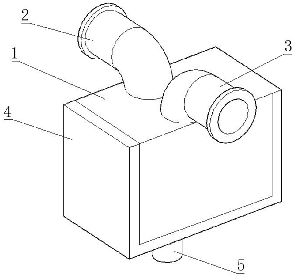
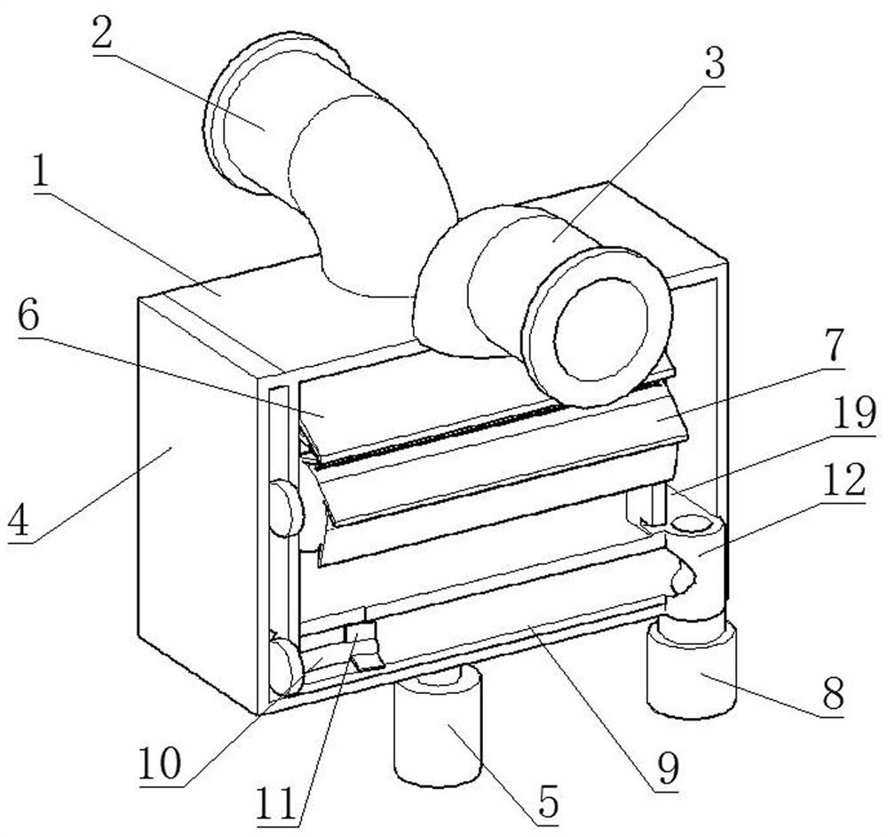
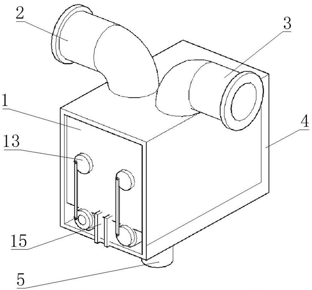
[0038] Such as Figure 1-4 As shown in the figure, a self-control valve for hot dirty gas used in industrial environmental protection equipment includes a valve body 1, and the two sides of the top of the valve body 1 are respectively connected with an intake pipe 2 and an exhaust pipe 3, which are fixed inside the valve body 1 and connected with a guide The straight plate 6 is fixedly connected with a diversion arc plate 17 at the bottom of the diversion straight plate 6, and the concave side of the diversion arc plate 17 is provided with a filter cartridge 7 that is rotatably connected with the valve body 1 through a rotating shaft 18 and a sealed bearing. The left side and the right side of the interior are symmetrical, and a water storage tank 19 is arranged at the right end of the valve body 1. The bottom end of the water storage tank 19 communicates with the interior of the valve body 1. The bottom end of the valve body 1 is slidably connected to a valve core 16, and the ...
Embodiment 2
[0041] Such as Figure 1-5 As shown in the figure, a self-control valve for hot dirty gas used in industrial environmental protection equipment includes a valve body 1, and the two sides of the top of the valve body 1 are respectively connected with an intake pipe 2 and an exhaust pipe 3, which are fixed inside the valve body 1 and connected with a guide The straight plate 6 is fixedly connected with a diversion arc plate 17 at the bottom of the diversion straight plate 6, and the concave side of the diversion arc plate 17 is provided with a filter cartridge 7 that is rotatably connected with the valve body 1 through a rotating shaft 18 and a sealed bearing. The left side and the right side of the interior are symmetrical, and a water storage tank 19 is arranged at the right end of the valve body 1. The bottom end of the water storage tank 19 communicates with the interior of the valve body 1. The bottom end of the valve body 1 is slidably connected to a valve core 16, and the ...
Embodiment 3
[0044] Such as Figure 1-6 As shown in the figure, a self-control valve for hot dirty gas used in industrial environmental protection equipment includes a valve body 1, and the two sides of the top of the valve body 1 are respectively connected with an intake pipe 2 and an exhaust pipe 3, which are fixed inside the valve body 1 and connected with a guide The straight plate 6 is fixedly connected with a diversion arc plate 17 at the bottom of the diversion straight plate 6, and the concave side of the diversion arc plate 17 is provided with a filter cartridge 7 that is rotatably connected with the valve body 1 through a rotating shaft 18 and a sealed bearing. The left side and the right side of the interior are symmetrical, and a water storage tank 19 is arranged at the right end of the valve body 1. The bottom end of the water storage tank 19 communicates with the interior of the valve body 1. The bottom end of the valve body 1 is slidably connected to a valve core 16, and the ...
PUM
 Abstract
Description
Claims
Application Information
 - R&D Engineer
- R&D Manager
- IP Professional
- Industry Leading Data Capabilities
- Powerful AI technology
- Patent DNA Extraction
Browse by: Latest US Patents, China's latest patents, Technical Efficacy Thesaurus, Application Domain, Technology Topic, Popular Technical Reports.
© 2024 PatSnap. All rights reserved.Legal|Privacy policy|Modern Slavery Act Transparency Statement|Sitemap|About US| Contact US: help@patsnap.com