Oil pumping rod guiding device

A technology of guiding device and sucker rod, which is applied in the direction of drill pipe, drilling equipment, earthwork drilling and production, etc. It can solve the problems of shortening the service life of the oil pipe, large rotation resistance of the guider, and wear of the oil pipe in the well, so as to avoid energy loss and facilitate The effect of deviation correction and length shortening

Active Publication Date: 2020-08-28
东营市三和石油装备有限公司
View PDF6 Cites 0 Cited by
  • Summary
  • Abstract
  • Description
  • Claims
  • Application Information

AI Technical Summary

Problems solved by technology

In addition to the torque, the sucker rod rotates in the deflected well section, but also bears a large bending moment. At this position, the sucker rod twists and turns once every revolution, and bears a large alternating load. If the pulling force and torque are very large, it is necessary to use a guide to connect at this time. The existing guide has a large rotation resistance, which increases power consumption and causes great wear to the tubing in the well, shortening the service life of the tubing.

Method used


Image

  • Oil pumping rod guiding device
  • Oil pumping rod guiding device
  • Oil pumping rod guiding device

Examples


specific Embodiment approach 1

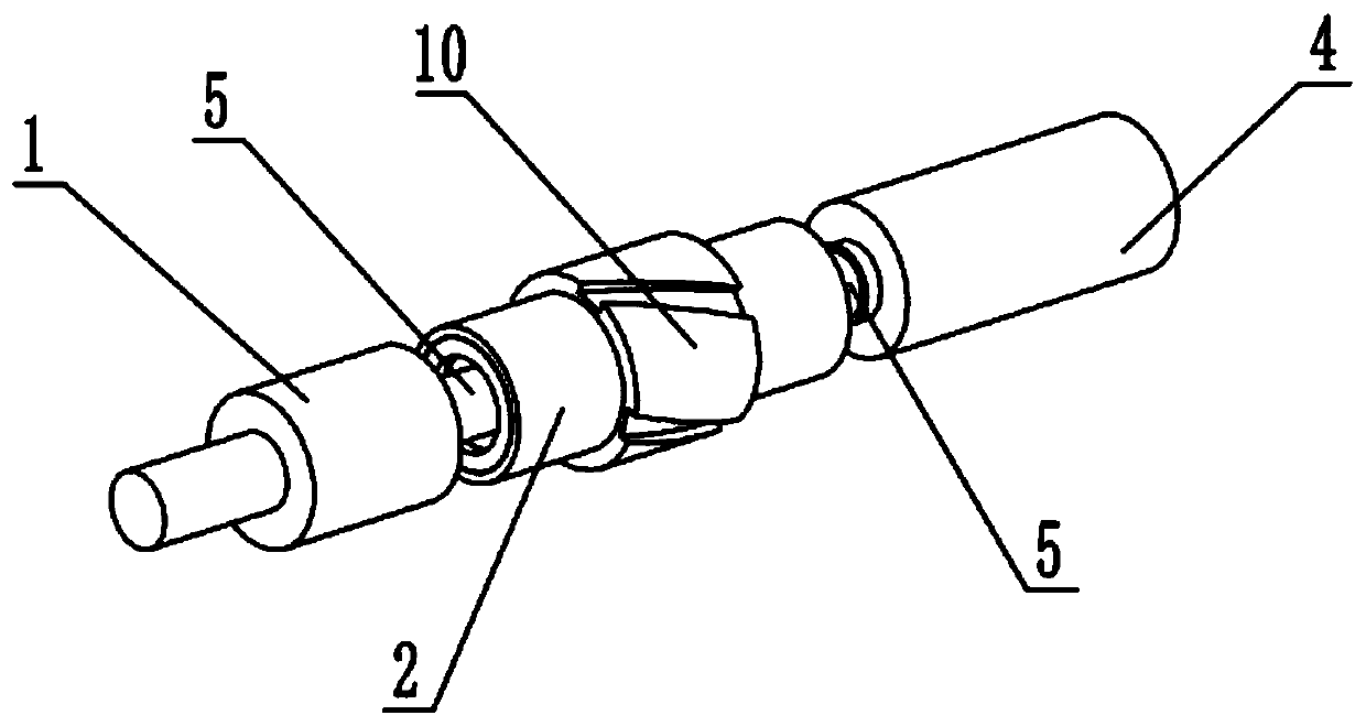
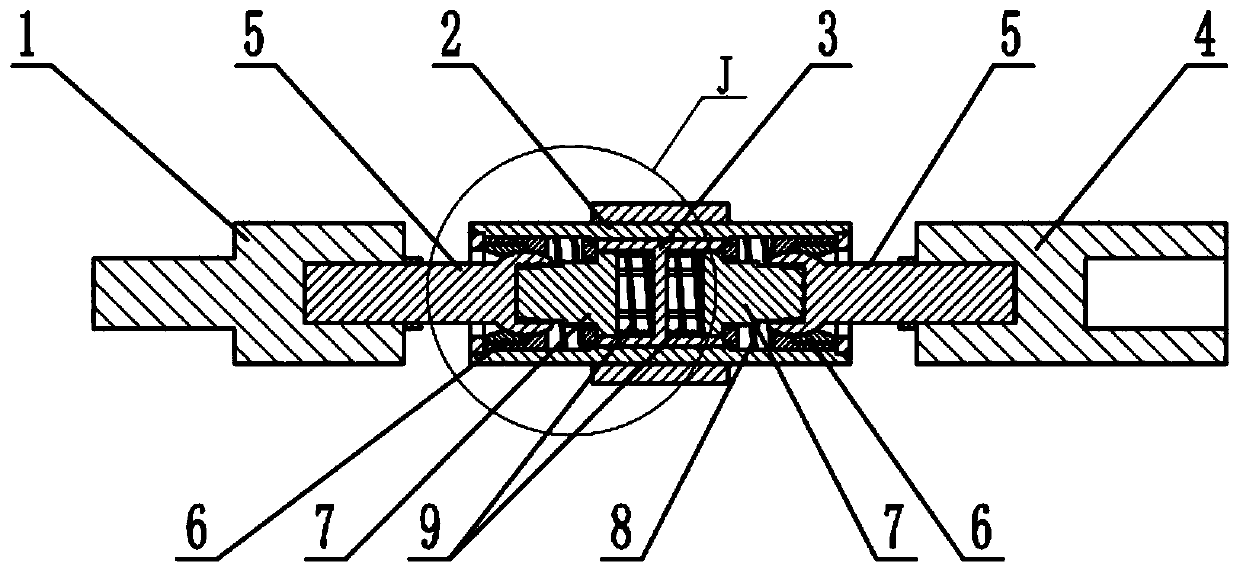
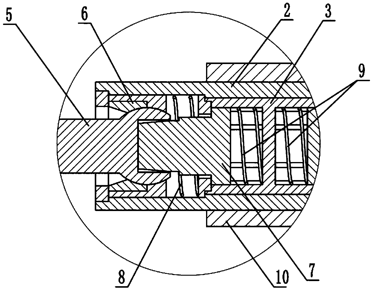
[0027] Such as Figure 1-9 As shown, a sucker rod guide device includes an outer connecting head I1, an outer sleeve 2, an inner rotating sleeve 3, an outer connecting head II4, a connecting shaft 5, a connecting shaft mounting sleeve 6, a transmission shaft 7, a spring I8, a spring II9 and The centralizer 10, the inner rotating sleeve 3 is rotatably connected to the middle inside the outer sleeve 2, the centralizer 10 is fixedly connected to the middle outside the outer sleeve 2, and both ends of the inner rotating sleeve 3 are slidably connected with transmission Shaft 7, the spring II 9 is provided with two, the two springs II 9 are respectively arranged at both ends of the inner rotating sleeve 3, the outer ends of the two springs II 9 are both pressed against the transmission shaft 7, the connecting shaft mounting sleeve 6 is provided with two, two connecting shaft mounting sleeves 6 are respectively slidably connected to the two ends of the outer casing 2, the said spring...

specific Embodiment approach 2

[0030] Such as Figure 1-9 As shown, the jacket 2 includes an outer connecting sleeve 2-1, a jacket stop ring 2-2, and a fixing sleeve 2-3. The fixing sleeve 2-3 is fixedly connected to the middle of the outer connecting sleeve 2-1, and the jacket stop ring 2 -2 is provided with two, the two outer casing stop rings 2-2 are respectively fixedly connected to the two ends of the outer connecting sleeve 2-1, and the centralizer 10 is fixedly connected to the middle part of the outer connecting sleeve 2-1;

[0031] The fixing sleeve 2-3 is used for the rotational installation of the inner rotating sleeve 3, and the outer sleeve retaining ring 2-2 is screwed on both ends of the outer connecting sleeve 2-1 for blocking the connecting shaft installation sleeve 6.

specific Embodiment approach 3

[0033] Such as Figure 1-9 As shown, the inner rotating sleeve 3 includes a rotating inner sleeve 3-1, a keyway 3-2, a middle partition 3-3, and a side baffle ring 3-4. The rotating inner sleeve 3-1 is rotatably connected to the fixed sleeve 2- In 3, the inner wall of the rotating inner sleeve 3-1 is evenly provided with a plurality of key grooves 3-2, the middle part of the rotating inner sleeve 3-1 is fixedly connected with the intermediate partition 3-3, and the side baffle ring 3-4 is provided with two , The two side baffle rings 3-4 are respectively fixedly connected to the two ends of the rotating inner sleeve 3-1, and the outer ends of the two side baffle rings 3-4 are both rotatably connected with the inner wall of the outer connecting sleeve 2-1. The above-mentioned springs I8 are respectively arranged at the two ends of the outer connecting sleeve 2-1, the inner parts of the two springs I8 tighten the two side baffle rings 3-4, and the two springs II9 are respectively...


PUM


Abstract

The invention relates to the field of oil natural gas and coalbed methane exploitation, in particular to an oil pumping rod guiding device. The oil pumping rod guiding device comprises an outer connecting head I, an outer sleeve, an inner rotating sleeve, an outer connecting head II, connecting shafts, connecting shaft mounting sleeves, transmission shafts, a spring I, a spring II and a centralizer. The inner rotating sleeve is rotationally connected to the middle in the outer sleeve. The centralizer is fixedly connected to the middle of the outer portion of the outer sleeve. The two ends of the inner rotating sleeve are slidably connected with the transmission shafts. The two connecting shaft mounting sleeves are arranged. The two connecting shaft mounting sleeves are slidably connected to the two ends in the outer sleeve. The two connecting shaft mounting sleeves both are internally and rotationally connected with the connecting shafts. The outer ends of the two connecting shafts arecorrespondingly and fixedly connected with the outer connecting head I and the outer connecting head II. The two connecting shafts are in clearance engagement transmission connection with the two transmission shafts. By the adoption of the oil pumping rod guiding device, the rotating resistance of the guiding device can be reduced, the power consumption is reduced, the wear of an oil pipe in a well is reduced, and the service life of the oil pipe is prolonged.

Description

Technical field [0001] The invention relates to the field of petroleum natural gas and coal-bed methane exploitation, in particular to a sucker rod guiding device. Background technique [0002] When mining coalbed methane, in the wells using screw pumps, sucker rods are used to transmit torque in order to reduce investment. During the drilling process, according to the drilling construction design requirements, to achieve the smooth target of the directional well, it is necessary to continuously correct the deviation in the transition section between the deflection point and the stable deflection point to meet the design requirements, so the full-angle change rate of the well section Both: the dogleg degree presents a large fluctuation. In addition to the torque that the sucker rod rotates in the deviated well section, it also bears a large bending moment. At this position, the sucker rod twists and flips every time it rotates, and bears a large alternating load. Large pulling ...

Claims


Application Information

Patent Timeline
Patent Type & Authority Applications(China)
IPC IPC(8): E21B17/10E21B17/02
CPCE21B17/1078E21B17/02
Inventor 朱善淼
Owner 东营市三和石油装备有限公司
Why Eureka
Try Eureka